CT — Umăr Stryker (MCB)
Sursă și prelucrare editorială
- Proveniență
- 1 referință declarată
- Fidelitatea preluării
- Nedocumentată
- Revizuire medicală
- Nedocumentată
Referințele declarate nu confirmă singure fidelitatea preluării sau aprobarea protocolului pentru utilizare locală.
Detalii despre surse și verificări
MCB Radiology — 15 Stryker Shoulder
- Ediție / versiune a sursei
- Neprecizată
- Pagină / secțiune
- Pagini: 1–11
- Relația cu protocolul
- Document original importat integral; atribuirea autorilor rămâne cea din PDF.
- Data consultării
- 2026-09-27
Prelucrarea acestei pagini
- Mod de prelucrare
- Titlu și navigare în română; documentul sursă în engleză.; PDF original integral, previzualizare și text extras automat; fără completarea parametrilor clinici lipsă.
- Adaptări față de sursă
- Nedocumentate; absența evidenței nu confirmă o preluare integrală.
- Responsabil pentru prelucrare
- Neprecizat
- Atribuire existentă în pagină
- MCB Radiology (portalul sursă). Această atribuire nu identifică automat autorul sursei sau revizorul medical.
- Versiunea paginii
- mcb-211c089d157c
- Actualizare declarată a paginii
- 2026-09-27 — distinctă de revizuirea medicală.
Verificarea fidelității: Nedocumentată
Revizuirea medicală: Nedocumentată
Documentul original MCB — Umăr Stryker
Protocol · 11 pagini · consultat la 2026-09-27.
Descarcă PDF-ul integral · Sursa MCB · Catalogul MCB pentru această modalitate
Instrucțiunile, valorile și ilustrațiile din documentul original sunt păstrate în engleză. Titlul și navigarea sunt în română.
Pagina 1
Pagina 2
Pagina 3
Pagina 4
Pagina 5
Pagina 6
Pagina 7
Pagina 8
Pagina 9
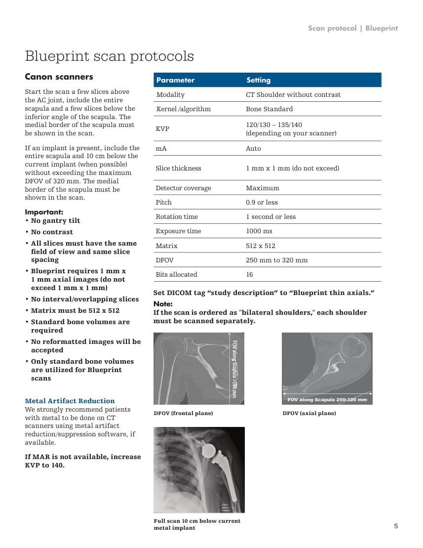
Pagina 10
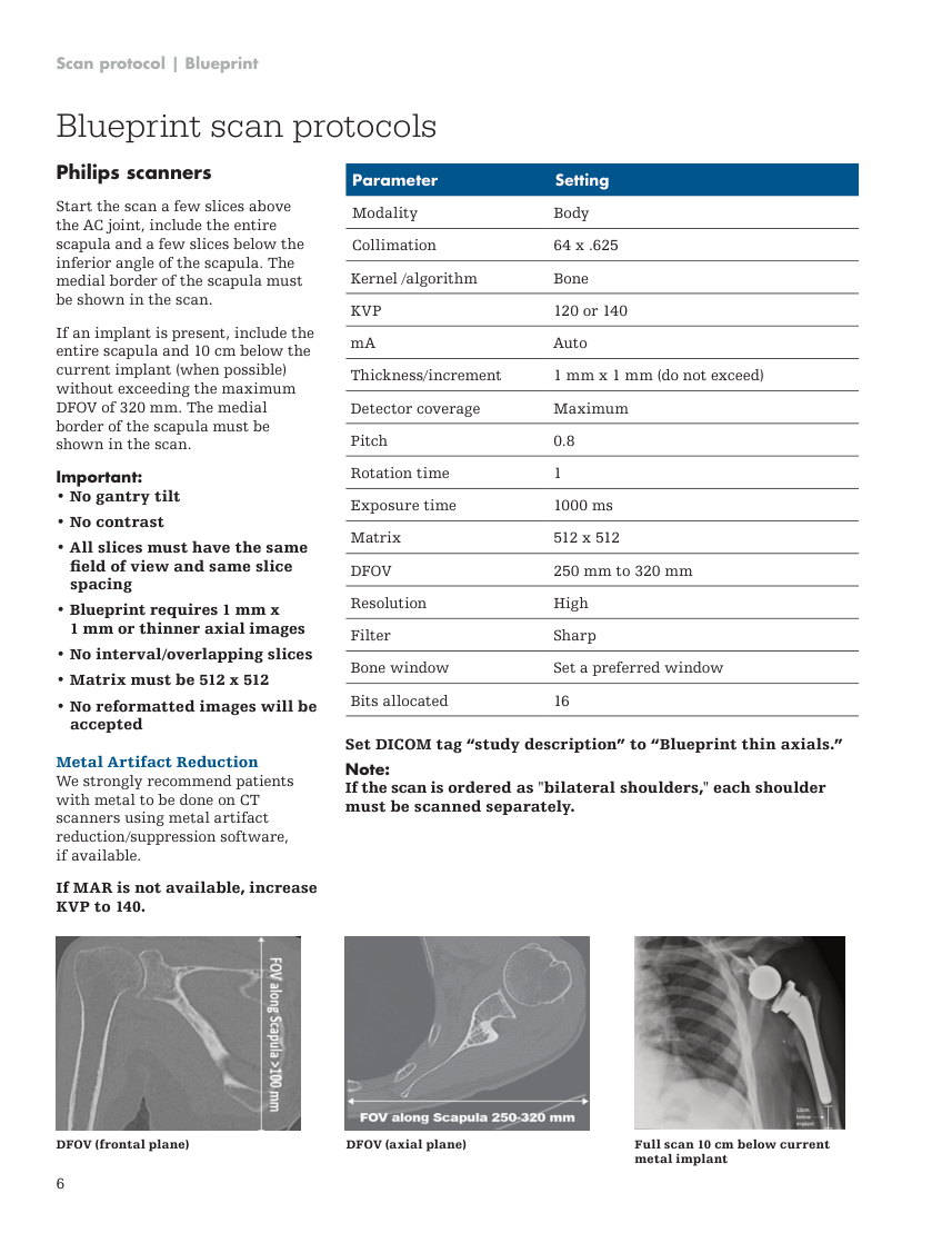
Pagina 11
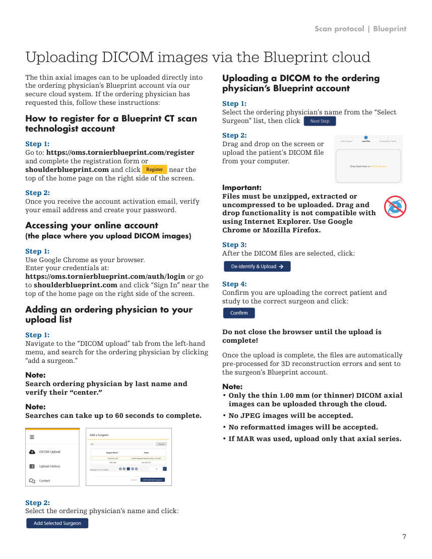
Textul documentului original
Pagina 1 — text în engleză
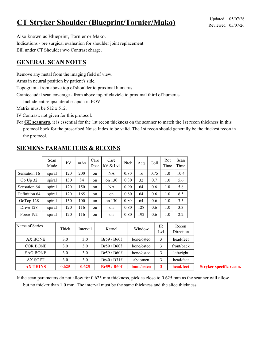
Updated 05/07/26 CT Stryker Shoulder (Blueprint/Tornier/Mako) Reviewed 05/07/26 Also known as Blueprint, Tornier or Mako. Indications - pre surgical evaluation for shoulder joint replacement. Bill under CT Shoulder w/o Contrast charge. GENERAL SCAN NOTES Remove any metal from the imaging field of view. Arms in neutral position by patient's side. Topogram - from above top of shoulder to proximal humerus. Craniocaudal scan coverage - from above top of clavicle to proximal third of humerus. Include entire ipsilateral scapula in FOV. Matrix must be 512 x 512. IV Contrast: not given for this protocol. For GE scanners, it is essential for the 1st recon thickness on the scanner to match the 1st recon thickness in this protocol book for the prescribed Noise Index to be valid. The 1st recon should generally be the thickest recon in the protocol. SIEMENS PARAMETERS & RECONS Scan
Care
Scan
Pitch Acq Coll Rot Mode kV mAs Care
Dose kV & Lvl Time Time Sensation 16 spiral 120 200 on NA 0.80 16 0.75 1.0 10.4 Go Up 32 spiral 130 84 on 0.80 32 0.7 1.0 5.6 on 130 Sensation 64 spiral 120 150 on NA 0.90 64 0.6 1.0 5.8 Definition 64 spiral 120 165 on 0.80 64 0.6 1.0 6.5 on GoTop 128 spiral 130 100 on on 130 0.80 64 0.6 1.0 3.3 Drive 128 spiral 120 116 on on 0.80 128 0.6 1.0 3.3 Force 192 spiral 120 116 on on 0.80 192 0.6 1.0 2.2 Name of Series Recon
Thick Interval Kernel Window IR
Lvl Direction AX BONE 3.0 3.0 Br59 / B60f bone/osteo 3 head/feet COR BONE 3.0 3.0 Br59 / B60f bone/osteo 3 front/back SAG BONE 3.0 3.0 Br59 / B60f bone/osteo 3 left/right AX SOFT 3.0 3.0 Br40 / B31f abdomen 3 head/feet Stryker specific recon. AX THINS 0.625 0.625 Br59 / B60f bone/osteo 3 head/feet If the scan parameters do not allow for 0.625 mm thickness, pick as close to 0.625 mm as the scanner will allow but no thicker than 1.0 mm. The interval must be the same thickness and the slice thickness.
Care
Scan
Pitch Acq Coll Rot Mode kV mAs Care
Dose kV & Lvl Time Time Sensation 16 spiral 120 200 on NA 0.80 16 0.75 1.0 10.4 Go Up 32 spiral 130 84 on 0.80 32 0.7 1.0 5.6 on 130 Sensation 64 spiral 120 150 on NA 0.90 64 0.6 1.0 5.8 Definition 64 spiral 120 165 on 0.80 64 0.6 1.0 6.5 on GoTop 128 spiral 130 100 on on 130 0.80 64 0.6 1.0 3.3 Drive 128 spiral 120 116 on on 0.80 128 0.6 1.0 3.3 Force 192 spiral 120 116 on on 0.80 192 0.6 1.0 2.2 Name of Series Recon
Thick Interval Kernel Window IR
Lvl Direction AX BONE 3.0 3.0 Br59 / B60f bone/osteo 3 head/feet COR BONE 3.0 3.0 Br59 / B60f bone/osteo 3 front/back SAG BONE 3.0 3.0 Br59 / B60f bone/osteo 3 left/right AX SOFT 3.0 3.0 Br40 / B31f abdomen 3 head/feet Stryker specific recon. AX THINS 0.625 0.625 Br59 / B60f bone/osteo 3 head/feet If the scan parameters do not allow for 0.625 mm thickness, pick as close to 0.625 mm as the scanner will allow but no thicker than 1.0 mm. The interval must be the same thickness and the slice thickness.
Pagina 2 — text în engleză
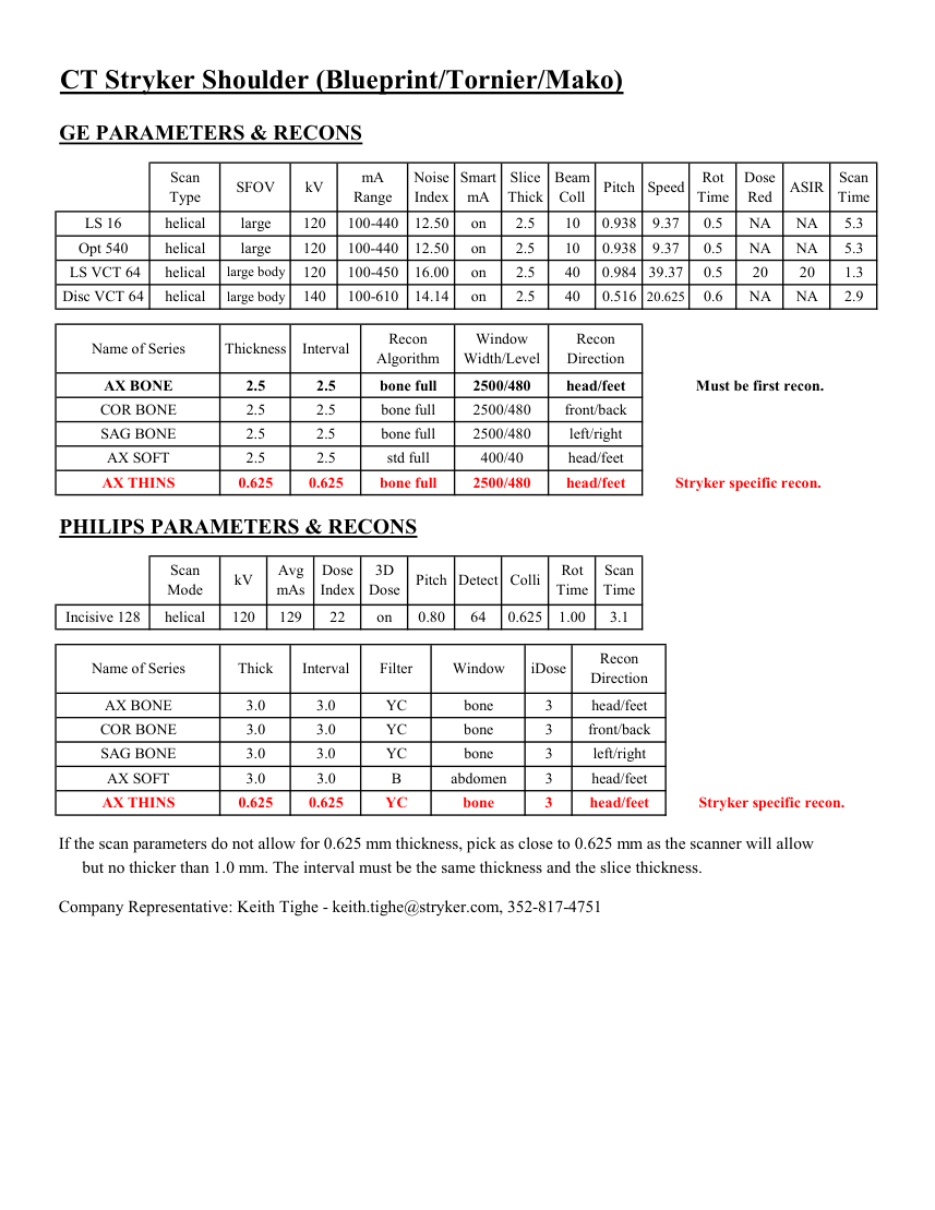
CT Stryker Shoulder (Blueprint/Tornier/Mako) GE PARAMETERS & RECONS Scan
Smart
Slice
Beam
Dose
Type SFOV kV mA
Range Noise
Index mA ASIR Scan
Thick Coll Pitch Speed Rot
Time Red Time 10 0.938 9.37 0.5 NA NA LS 16 helical large 120 100-440 12.50 on 2.5 5.3 Opt 540 helical large 120 100-440 12.50 on 2.5 10 0.938 9.37 0.5 NA NA 5.3 on 2.5 40 0.984 39.37 0.5 LS VCT 64 helical large body 120 100-450 16.00 20 20 1.3 Disc VCT 64 helical large body 140 100-610 14.14 on 2.5 40 0.516 NA 20.625 0.6 NA 2.9 Window
Recon Name of Series Thickness Interval Recon
Algorithm Width/Level Direction AX BONE 2.5 2.5 bone full 2500/480 head/feet Must be first recon. COR BONE 2.5 2.5 bone full 2500/480 front/back SAG BONE 2.5 2.5 bone full 2500/480 left/right AX SOFT 2.5 2.5 std full 400/40 head/feet AX THINS 0.625 0.625 bone full 2500/480 head/feet Stryker specific recon. PHILIPS PARAMETERS & RECONS Scan
Dose
3D
Rot Scan
Mode kV Avg
mAs Index Dose Pitch Detect Colli Time Time Incisive 128 helical 120 129 22 on 0.80 64 0.625 1.00 3.1 Name of Series Thick Interval Filter Window iDose Recon
Direction AX BONE 3.0 3.0 YC bone 3 head/feet COR BONE 3.0 3.0 YC bone 3 front/back SAG BONE 3.0 3.0 YC bone 3 left/right AX SOFT 3.0 3.0 B abdomen 3 head/feet head/feet Stryker specific recon. AX THINS 0.625 0.625 YC bone 3 If the scan parameters do not allow for 0.625 mm thickness, pick as close to 0.625 mm as the scanner will allow but no thicker than 1.0 mm. The interval must be the same thickness and the slice thickness. Company Representative: Keith Tighe - [email protected], 352-817-4751
Smart
Slice
Beam
Dose
Type SFOV kV mA
Range Noise
Index mA ASIR Scan
Thick Coll Pitch Speed Rot
Time Red Time 10 0.938 9.37 0.5 NA NA LS 16 helical large 120 100-440 12.50 on 2.5 5.3 Opt 540 helical large 120 100-440 12.50 on 2.5 10 0.938 9.37 0.5 NA NA 5.3 on 2.5 40 0.984 39.37 0.5 LS VCT 64 helical large body 120 100-450 16.00 20 20 1.3 Disc VCT 64 helical large body 140 100-610 14.14 on 2.5 40 0.516 NA 20.625 0.6 NA 2.9 Window
Recon Name of Series Thickness Interval Recon
Algorithm Width/Level Direction AX BONE 2.5 2.5 bone full 2500/480 head/feet Must be first recon. COR BONE 2.5 2.5 bone full 2500/480 front/back SAG BONE 2.5 2.5 bone full 2500/480 left/right AX SOFT 2.5 2.5 std full 400/40 head/feet AX THINS 0.625 0.625 bone full 2500/480 head/feet Stryker specific recon. PHILIPS PARAMETERS & RECONS Scan
Dose
3D
Rot Scan
Mode kV Avg
mAs Index Dose Pitch Detect Colli Time Time Incisive 128 helical 120 129 22 on 0.80 64 0.625 1.00 3.1 Name of Series Thick Interval Filter Window iDose Recon
Direction AX BONE 3.0 3.0 YC bone 3 head/feet COR BONE 3.0 3.0 YC bone 3 front/back SAG BONE 3.0 3.0 YC bone 3 left/right AX SOFT 3.0 3.0 B abdomen 3 head/feet head/feet Stryker specific recon. AX THINS 0.625 0.625 YC bone 3 If the scan parameters do not allow for 0.625 mm thickness, pick as close to 0.625 mm as the scanner will allow but no thicker than 1.0 mm. The interval must be the same thickness and the slice thickness. Company Representative: Keith Tighe - [email protected], 352-817-4751
Pagina 3 — text în engleză
® Blueprint Scan protocol
Pagina 4 — text în engleză
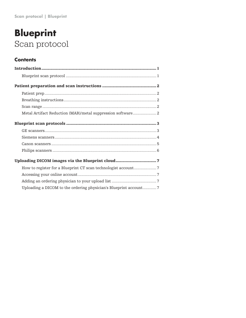
Scan protocol | Blueprint Blueprint Scan protocol Contents Introduction. ...................................................................................................... 1 Blueprint scan protocol..................................................................................1 Patient preparation and scan instructions................................................. 2 Patient prep. ....................................................................................................2 Breathing instructions. ...................................................................................2 Scan range.......................................................................................................2 Metal Artifact Reduction (MAR)/metal suppression software. ..................... 2 Blueprint scan protocols................................................................................. 3 GE scanners. ....................................................................................................3 Siemens scanners. ...........................................................................................4 Canon scanners...............................................................................................5 Philips scanners..............................................................................................6 Uploading DICOM images via the Blueprint cloud. .................................... 7 How to register for a Blueprint CT scan technologist account. .................... 7 Accessing your online account.......................................................................7 Adding an ordering physician to your upload list......................................... 7 Uploading a DICOM to the ordering physician's Blueprint account. ............ 7
Pagina 5 — text în engleză
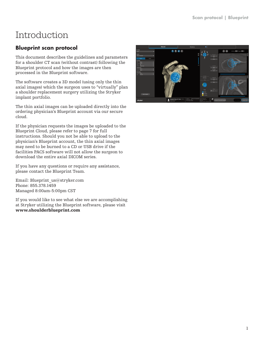
Scan protocol | Blueprint Introduction Blueprint scan protocol This document describes the guidelines and parameters for a shoulder CT scan (without contrast) following the Blueprint protocol and how the images are then processed in the Blueprint software. The software creates a 3D model (using only the thin axial images) which the surgeon uses to “virtually” plan a shoulder replacement surgery utilizing the Stryker implant portfolio. The thin axial images can be uploaded directly into the ordering physician’s Blueprint account via our secure cloud. If the physician requests the images be uploaded to the Blueprint Cloud, please refer to page 7 for full instructions. Should you not be able to upload to the physician’s Blueprint account, the thin axial images may need to be burned to a CD or USB drive if the facilities PACS software will not allow the surgeon to download the entire axial DICOM series. If you have any questions or require any assistance, please contact the Blueprint Team. Email: [email protected] Phone: 855.378.1459 Managed 8:00am-5:00pm CST If you would like to see what else we are accomplishing at Stryker utilizing the Blueprint software, please visit www.shoulderblueprint.com 1
Pagina 6 — text în engleză
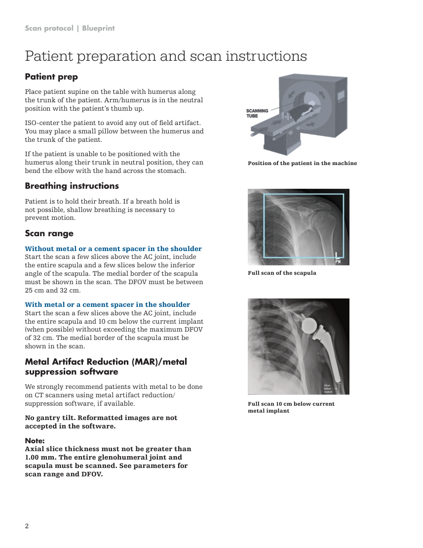
Scan protocol | Blueprint Patient preparation and scan instructions Patient prep Place patient supine on the table with humerus along the trunk of the patient. Arm/humerus is in the neutral position with the patient’s thumb up. ISO-center the patient to avoid any out of field artifact. You may place a small pillow between the humerus and the trunk of the patient. Position of the patient in the machine If the patient is unable to be positioned with the humerus along their trunk in neutral position, they can bend the elbow with the hand across the stomach. Breathing instructions Patient is to hold their breath. If a breath hold is not possible, shallow breathing is necessary to prevent motion. Scan range Full scan of the scapula Without metal or a cement spacer in the shoulder Start the scan a few slices above the AC joint, include the entire scapula and a few slices below the inferior angle of the scapula. The medial border of the scapula must be shown in the scan. The DFOV must be between 25 cm and 32 cm. With metal or a cement spacer in the shoulder Start the scan a few slices above the AC joint, include the entire scapula and 10 cm below the current implant (when possible) without exceeding the maximum DFOV of 32 cm. The medial border of the scapula must be shown in the scan. Metal Artifact Reduction (MAR)/metal suppression software We strongly recommend patients with metal to be done on CT scanners using metal artifact reduction/ suppression software, if available. Full scan 10 cm below current metal implant No gantry tilt. Reformatted images are not accepted in the software. Note: Axial slice thickness must not be greater than 1.00 mm. The entire glenohumeral joint and scapula must be scanned. See parameters for scan range and DFOV. 2
Pagina 7 — text în engleză
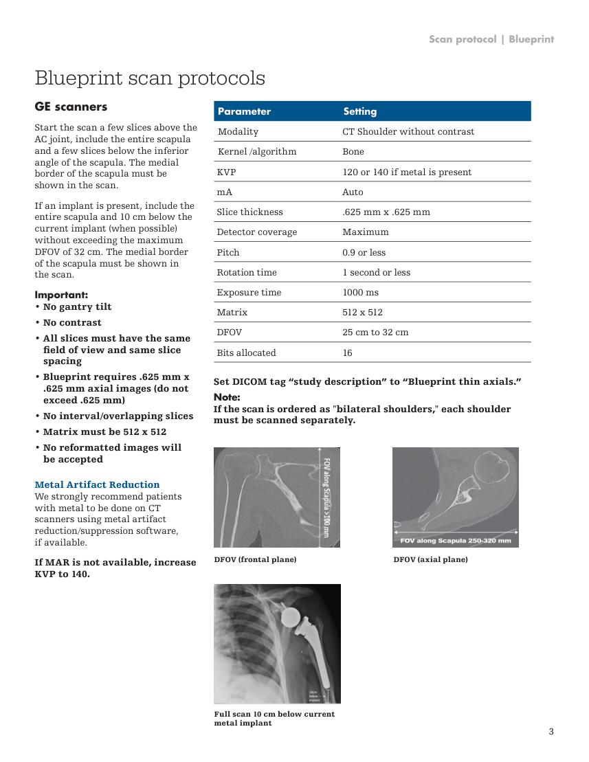
Scan protocol | Blueprint Blueprint scan protocols GE scanners Parameter Setting Modality CT Shoulder without contrast Kernel /algorithm Bone KVP 120 or 140 if metal is present Start the scan a few slices above the AC joint, include the entire scapula and a few slices below the inferior angle of the scapula. The medial border of the scapula must be shown in the scan. mA Auto Slice thickness .625 mm x .625 mm Detector coverage Maximum Pitch 0.9 or less Rotation time 1 second or less If an implant is present, include the entire scapula and 10 cm below the current implant (when possible) without exceeding the maximum DFOV of 32 cm. The medial border of the scapula must be shown in the scan. Exposure time 1000 ms Important: • No gantry tilt Matrix 512 x 512 • No contrast DFOV 25 cm to 32 cm • All slices must have the same Bits allocated 16 field of view and same slice spacing • Blueprint requires .625 mm x Set DICOM tag “study description” to “Blueprint thin axials.” .625 mm axial images (do not exceed .625 mm) • No interval/overlapping slices Note: If the scan is ordered as "bilateral shoulders," each shoulder must be scanned separately. • Matrix must be 512 x 512 • No reformatted images will be accepted Metal Artifact Reduction We strongly recommend patients with metal to be done on CT scanners using metal artifact reduction/suppression software, if available. DFOV (frontal plane) DFOV (axial plane) If MAR is not available, increase KVP to 140. Full scan 10 cm below current metal implant 3
Pagina 8 — text în engleză
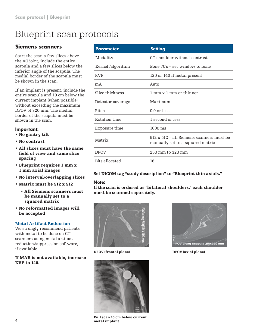
Scan protocol | Blueprint Blueprint scan protocols Siemens scanners Parameter Setting Modality CT shoulder without contrast Kernel /algorithm Bone 70's – set window to bone KVP 120 or 140 if metal present Start the scan a few slices above the AC joint, include the entire scapula and a few slices below the inferior angle of the scapula. The medial border of the scapula must be shown in the scan. mA Auto Slice thickness 1 mm x 1 mm or thinner Detector coverage Maximum Pitch 0.9 or less Rotation time 1 second or less If an implant is present, include the entire scapula and 10 cm below the current implant (when possible) without exceeding the maximum DFOV of 320 mm. The medial border of the scapula must be shown in the scan. Exposure time 1000 ms Important: • No gantry tilt • No contrast Matrix 512 x 512 – all Siemens scanners must be manually set to a squared matrix • All slices must have the same DFOV 250 mm to 320 mm field of view and same slice spacing Bits allocated 16 • Blueprint requires 1 mm x 1 mm axial images Set DICOM tag “study description” to “Blueprint thin axials.” • No interval/overlapping slices • Matrix must be 512 x 512 • All Siemens scanners must Note: If the scan is ordered as "bilateral shoulders," each shoulder must be scanned separately. be manually set to a squared matrix • No reformatted images will be accepted Metal Artifact Reduction We strongly recommend patients with metal to be done on CT scanners using metal artifact reduction/suppression software, if available. DFOV (frontal plane) DFOV (axial plane) If MAR is not available, increase KVP to 140. 4 Full scan 10 cm below current metal implant
Pagina 9 — text în engleză
Scan protocol | Blueprint Blueprint scan protocols Canon scanners Parameter Setting Modality CT Shoulder without contrast Kernel /algorithm Bone Standard KVP 120/130 – 135/140 (depending on your scanner) Start the scan a few slices above the AC joint, include the entire scapula and a few slices below the inferior angle of the scapula. The medial border of the scapula must be shown in the scan. mA Auto Slice thickness 1 mm x 1 mm (do not exceed) Detector coverage Maximum If an implant is present, include the entire scapula and 10 cm below the current implant (when possible) without exceeding the maximum DFOV of 320 mm. The medial border of the scapula must be shown in the scan. Pitch 0.9 or less Rotation time 1 second or less Important: • No gantry tilt Exposure time 1000 ms • No contrast • All slices must have the same Matrix 512 x 512 field of view and same slice spacing DFOV 250 mm to 320 mm • Blueprint requires 1 mm x Bits allocated 16 1 mm axial images (do not exceed 1 mm x 1 mm) Set DICOM tag “study description” to “Blueprint thin axials.” • No interval/overlapping slices • Matrix must be 512 x 512 Note: If the scan is ordered as "bilateral shoulders," each shoulder must be scanned separately. • Standard bone volumes are required • No reformatted images will be accepted • Only standard bone volumes are utilized for Blueprint scans DFOV (frontal plane) DFOV (axial plane) Metal Artifact Reduction We strongly recommend patients with metal to be done on CT scanners using metal artifact reduction/suppression software, if available. If MAR is not available, increase KVP to 140. 5 Full scan 10 cm below current metal implant
Pagina 10 — text în engleză
Scan protocol | Blueprint Blueprint scan protocols Philips scanners Parameter Setting Modality Body Collimation 64 x .625 Kernel /algorithm Bone Start the scan a few slices above the AC joint, include the entire scapula and a few slices below the inferior angle of the scapula. The medial border of the scapula must be shown in the scan. KVP 120 or 140 mA Auto Thickness/increment 1 mm x 1 mm (do not exceed) Detector coverage Maximum Pitch 0.8 If an implant is present, include the entire scapula and 10 cm below the current implant (when possible) without exceeding the maximum DFOV of 320 mm. The medial border of the scapula must be shown in the scan. Rotation time 1 Important: • No gantry tilt Exposure time 1000 ms • No contrast Matrix 512 x 512 • All slices must have the same DFOV 250 mm to 320 mm field of view and same slice spacing Resolution High • Blueprint requires 1 mm x 1 mm or thinner axial images Filter Sharp • No interval/overlapping slices Bone window Set a preferred window • Matrix must be 512 x 512 Bits allocated 16 • No reformatted images will be accepted Set DICOM tag “study description” to “Blueprint thin axials.” Note: If the scan is ordered as "bilateral shoulders," each shoulder must be scanned separately. Metal Artifact Reduction We strongly recommend patients with metal to be done on CT scanners using metal artifact reduction/suppression software, if available. If MAR is not available, increase KVP to 140. DFOV (frontal plane) DFOV (axial plane) Full scan 10 cm below current metal implant 6
Pagina 11 — text în engleză
Scan protocol | Blueprint Uploading DICOM images via the Blueprint cloud Uploading a DICOM to the ordering physician’ s Blueprint account The thin axial images can to be uploaded directly into the ordering physician’s Blueprint account via our secure cloud system. If the ordering physician has requested this, follow these instructions: Step 1: Select the ordering physician’s name from the “Select Surgeon” list, then click How to register for a Blueprint CT scan technologist account Step 2: Drag and drop on the screen or upload the patient’s DICOM file from your computer. Step 1: Go to: https://oms.tornierblueprint.com/register and complete the registration form or shoulderblueprint.com and click near the top of the home page on the right side of the screen. Step 2: Once you receive the account activation email, verify your email address and create your password. Important: Files must be unzipped, extracted or uncompressed to be uploaded. Drag and drop functionality is not compatible with using Internet Explorer. Use Google Chrome or Mozilla Firefox. Accessing your online account (the place where you upload DICOM images) Step 3: After the DICOM files are selected, click: Step 1: Use Google Chrome as your browser. Enter your credentials at: https://oms.tornierblueprint.com/auth/login or go to shoulderblueprint.com and click “Sign In” near the top of the home page on the right side of the screen. Step 4: Confirm you are uploading the correct patient and study to the correct surgeon and click: Adding an ordering physician to your upload list Do not close the browser until the upload is complete! Step 1: Navigate to the “DICOM upload” tab from the left-hand menu, and search for the ordering physician by clicking “add a surgeon.” Once the upload is complete, the files are automatically pre-processed for 3D reconstruction errors and sent to the surgeon’s Blueprint account. Note: Search ordering physician by last name and verify their “center.” Note: • Only the thin 1.00 mm (or thinner) DICOM axial images can be uploaded through the cloud. Note: Searches can take up to 60 seconds to complete. • No JPEG images will be accepted. • No reformatted images will be accepted. • If MAR was used, upload only that axial series. Step 2: Select the ordering physician’s name and click: 7