CT — Șold Mako (MCB)
Sursă și prelucrare editorială
- Proveniență
- 1 referință declarată
- Fidelitatea preluării
- Nedocumentată
- Revizuire medicală
- Nedocumentată
Referințele declarate nu confirmă singure fidelitatea preluării sau aprobarea protocolului pentru utilizare locală.
Detalii despre surse și verificări
MCB Radiology — 16 Mako Hip
- Ediție / versiune a sursei
- Neprecizată
- Pagină / secțiune
- Pagini: 1–6
- Relația cu protocolul
- Document original importat integral; atribuirea autorilor rămâne cea din PDF.
- Data consultării
- 2026-09-27
Prelucrarea acestei pagini
- Mod de prelucrare
- Titlu și navigare în română; documentul sursă în engleză.; PDF original integral, previzualizare și text extras automat; fără completarea parametrilor clinici lipsă.
- Adaptări față de sursă
- Nedocumentate; absența evidenței nu confirmă o preluare integrală.
- Responsabil pentru prelucrare
- Neprecizat
- Atribuire existentă în pagină
- MCB Radiology (portalul sursă). Această atribuire nu identifică automat autorul sursei sau revizorul medical.
- Versiunea paginii
- mcb-3eac5aefc621
- Actualizare declarată a paginii
- 2026-09-27 — distinctă de revizuirea medicală.
Verificarea fidelității: Nedocumentată
Revizuirea medicală: Nedocumentată
Documentul original MCB — Șold Mako
Protocol · 6 pagini · consultat la 2026-09-27.
Descarcă PDF-ul integral · Sursa MCB · Catalogul MCB pentru această modalitate
Instrucțiunile, valorile și ilustrațiile din documentul original sunt păstrate în engleză. Titlul și navigarea sunt în română.
Pagina 1
Pagina 2
Pagina 3
Pagina 4
Pagina 5
Pagina 6
Textul documentului original
Pagina 1 — text în engleză
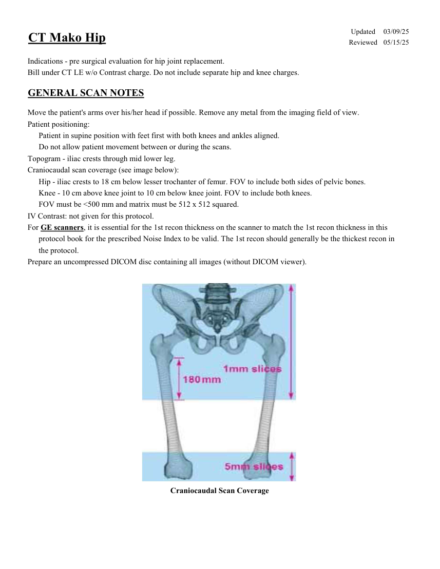
Updated 03/09/25 CT Mako Hip Reviewed 05/15/25 Indications - pre surgical evaluation for hip joint replacement. Bill under CT LE w/o Contrast charge. Do not include separate hip and knee charges. GENERAL SCAN NOTES Move the patient's arms over his/her head if possible. Remove any metal from the imaging field of view. Patient positioning: Patient in supine position with feet first with both knees and ankles aligned. Do not allow patient movement between or during the scans. Topogram - iliac crests through mid lower leg. Craniocaudal scan coverage (see image below): Hip - iliac crests to 18 cm below lesser trochanter of femur. FOV to include both sides of pelvic bones. Knee - 10 cm above knee joint to 10 cm below knee joint. FOV to include both knees. FOV must be <500 mm and matrix must be 512 x 512 squared. IV Contrast: not given for this protocol. For GE scanners, it is essential for the 1st recon thickness on the scanner to match the 1st recon thickness in this protocol book for the prescribed Noise Index to be valid. The 1st recon should generally be the thickest recon in the protocol. Prepare an uncompressed DICOM disc containing all images (without DICOM viewer). Craniocaudal Scan Coverage
Pagina 2 — text în engleză
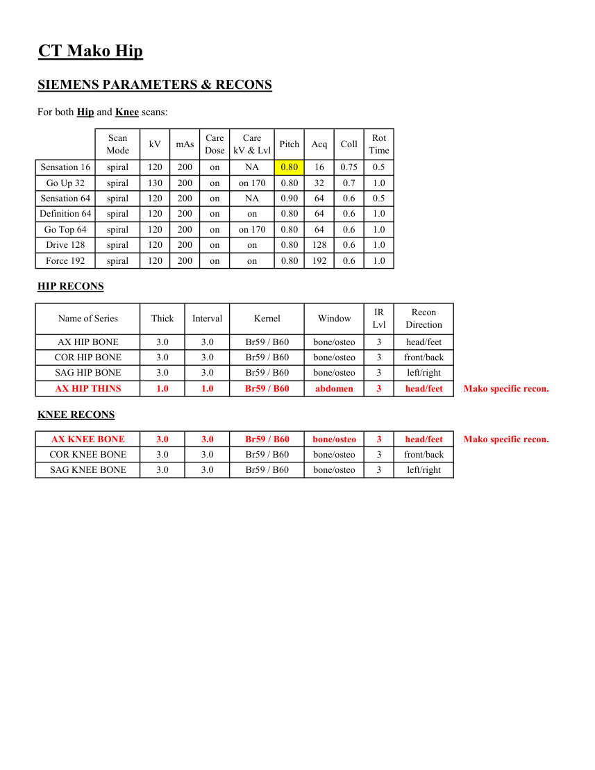
CT Mako Hip SIEMENS PARAMETERS & RECONS For both Hip and Knee scans: Scan
Care
Acq Coll Rot Mode kV mAs Care
Dose kV & Lvl Pitch Time Sensation 16 spiral 120 200 on NA 0.80 16 0.75 0.5 Go Up 32 spiral 130 200 on on 170 0.80 32 0.7 1.0 Sensation 64 spiral 120 200 on 0.90 64 0.6 0.5 NA Definition 64 spiral 120 200 on on 0.80 64 0.6 1.0 Go Top 64 spiral 120 200 on 0.80 64 0.6 1.0 on 170 Drive 128 spiral 120 200 on on 0.80 128 0.6 1.0 Force 192 spiral 120 200 on on 0.80 192 0.6 1.0 HIP RECONS IR
Recon
Name of Series Thick Interval Kernel Window Lvl Direction AX HIP BONE 3.0 3.0 Br59 / B60 bone/osteo 3 head/feet COR HIP BONE 3.0 3.0 Br59 / B60 bone/osteo 3 front/back SAG HIP BONE 3.0 3.0 Br59 / B60 bone/osteo 3 left/right head/feet AX HIP THINS 1.0 1.0 Br59 / B60 abdomen 3 Mako specific recon. KNEE RECONS AX KNEE BONE 3.0 3.0 Br59 / B60 bone/osteo 3 head/feet Mako specific recon. COR KNEE BONE 3.0 3.0 Br59 / B60 bone/osteo 3 front/back SAG KNEE BONE 3.0 3.0 Br59 / B60 bone/osteo 3 left/right
Care
Acq Coll Rot Mode kV mAs Care
Dose kV & Lvl Pitch Time Sensation 16 spiral 120 200 on NA 0.80 16 0.75 0.5 Go Up 32 spiral 130 200 on on 170 0.80 32 0.7 1.0 Sensation 64 spiral 120 200 on 0.90 64 0.6 0.5 NA Definition 64 spiral 120 200 on on 0.80 64 0.6 1.0 Go Top 64 spiral 120 200 on 0.80 64 0.6 1.0 on 170 Drive 128 spiral 120 200 on on 0.80 128 0.6 1.0 Force 192 spiral 120 200 on on 0.80 192 0.6 1.0 HIP RECONS IR
Recon
Name of Series Thick Interval Kernel Window Lvl Direction AX HIP BONE 3.0 3.0 Br59 / B60 bone/osteo 3 head/feet COR HIP BONE 3.0 3.0 Br59 / B60 bone/osteo 3 front/back SAG HIP BONE 3.0 3.0 Br59 / B60 bone/osteo 3 left/right head/feet AX HIP THINS 1.0 1.0 Br59 / B60 abdomen 3 Mako specific recon. KNEE RECONS AX KNEE BONE 3.0 3.0 Br59 / B60 bone/osteo 3 head/feet Mako specific recon. COR KNEE BONE 3.0 3.0 Br59 / B60 bone/osteo 3 front/back SAG KNEE BONE 3.0 3.0 Br59 / B60 bone/osteo 3 left/right
Pagina 3 — text în engleză
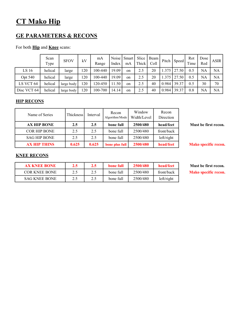
CT Mako Hip GE PARAMETERS & RECONS For both Hip and Knee scans: Scan
Smart
Slice
Beam
Dose
Type SFOV kV mA
Range Noise
Index mA Thick Coll Pitch Speed Rot
Time Red ASIR on 2.5 20 1.375 27.50 0.5 LS 16 helical large 120 100-440 19.09 NA NA Opt 540 helical large 120 100-440 19.09 on 2.5 20 1.375 27.50 0.5 NA NA LS VCT 64 helical large body 120 120-450 11.50 on 2.5 40 0.984 39.37 0.5 30 70 0.984 39.37 0.8 NA NA Disc VCT 64 helical large body 120 100-700 14.14 on 2.5 40 HIP RECONS Window
Recon Recon
Name of Series Thickness Interval Algorithm/Mode Width/Level Direction AX HIP BONE 2.5 2.5 bone full 2500/480 head/feet Must be first recon. COR HIP BONE 2.5 2.5 bone full 2500/480 front/back SAG HIP BONE 2.5 2.5 bone full 2500/480 left/right AX HIP THINS 0.625 0.625 bone plus full 2500/480 head/feet Mako specific recon. KNEE RECONS AX KNEE BONE 2.5 2.5 bone full 2500/480 head/feet Must be first recon. COR KNEE BONE 2.5 2.5 bone full 2500/480 front/back Mako specific recon. SAG KNEE BONE 2.5 2.5 bone full 2500/480 left/right
Smart
Slice
Beam
Dose
Type SFOV kV mA
Range Noise
Index mA Thick Coll Pitch Speed Rot
Time Red ASIR on 2.5 20 1.375 27.50 0.5 LS 16 helical large 120 100-440 19.09 NA NA Opt 540 helical large 120 100-440 19.09 on 2.5 20 1.375 27.50 0.5 NA NA LS VCT 64 helical large body 120 120-450 11.50 on 2.5 40 0.984 39.37 0.5 30 70 0.984 39.37 0.8 NA NA Disc VCT 64 helical large body 120 100-700 14.14 on 2.5 40 HIP RECONS Window
Recon Recon
Name of Series Thickness Interval Algorithm/Mode Width/Level Direction AX HIP BONE 2.5 2.5 bone full 2500/480 head/feet Must be first recon. COR HIP BONE 2.5 2.5 bone full 2500/480 front/back SAG HIP BONE 2.5 2.5 bone full 2500/480 left/right AX HIP THINS 0.625 0.625 bone plus full 2500/480 head/feet Mako specific recon. KNEE RECONS AX KNEE BONE 2.5 2.5 bone full 2500/480 head/feet Must be first recon. COR KNEE BONE 2.5 2.5 bone full 2500/480 front/back Mako specific recon. SAG KNEE BONE 2.5 2.5 bone full 2500/480 left/right
Pagina 4 — text în engleză
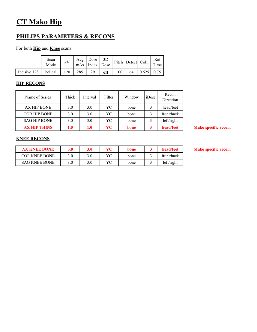
CT Mako Hip PHILIPS PARAMETERS & RECONS For both Hip and Knee scans: Scan
Dose
3D
Rot Mode kV Avg
mAs Index Dose Pitch Detect Colli Time 0.625 0.75 Incisive 128 helical 120 285 29 off 1.00 64 HIP RECONS Name of Series Thick Interval Filter Window iDose Recon
Direction AX HIP BONE 3.0 3.0 YC bone 3 head/feet COR HIP BONE 3.0 3.0 YC bone 3 front/back SAG HIP BONE 3.0 3.0 YC bone 3 left/right AX HIP THINS 1.0 1.0 YC bone 3 head/feet Mako specific recon. KNEE RECONS AX KNEE BONE 3.0 3.0 YC bone 3 head/feet Mako specific recon. COR KNEE BONE 3.0 3.0 YC bone 3 front/back SAG KNEE BONE 3.0 3.0 YC bone 3 left/right
Dose
3D
Rot Mode kV Avg
mAs Index Dose Pitch Detect Colli Time 0.625 0.75 Incisive 128 helical 120 285 29 off 1.00 64 HIP RECONS Name of Series Thick Interval Filter Window iDose Recon
Direction AX HIP BONE 3.0 3.0 YC bone 3 head/feet COR HIP BONE 3.0 3.0 YC bone 3 front/back SAG HIP BONE 3.0 3.0 YC bone 3 left/right AX HIP THINS 1.0 1.0 YC bone 3 head/feet Mako specific recon. KNEE RECONS AX KNEE BONE 3.0 3.0 YC bone 3 head/feet Mako specific recon. COR KNEE BONE 3.0 3.0 YC bone 3 front/back SAG KNEE BONE 3.0 3.0 YC bone 3 left/right
Pagina 5 — text în engleză
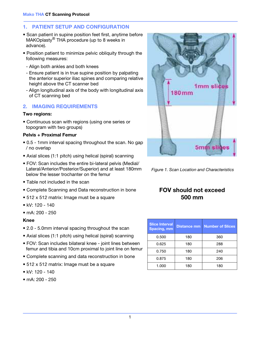
Mako THA CT Scanning Protocol 1. PATIENT SETUP AND CONFIGURATION • Scan patient in supine position feet first, anytime before MAKOplasty® THA procedure (up to 8 weeks in advance). • Position patient to minimize pelvic obliquity through the following measures: - Align both ankles and both knees - Ensure patient is in true supine position by palpating the anterior superior iliac spines and comparing relative height above the CT scanner bed - Align longitudinal axis of the body with longitudinal axis of CT scanning bed 2. IMAGING REQUIREMENTS Two regions: • Continuous scan with regions (using one series or topogram with two groups) Pelvis + Proximal Femur • 0.5 - 1mm interval spacing throughout the scan. No gap / no overlap • Axial slices (1:1 pitch) using helical (spiral) scanning Figure 1. Scan Location and Characteristics • FOV: Scan includes the entire bi-lateral pelvis (Medial/ Lateral/Anterior/Posterior/Superior) and at least 180mm below the lesser trochanter on the femur • Table not included in the scan • Complete Scanning and Data reconstruction in bone • 512 x 512 matrix: Image must be a square FOV should not exceed 500 mm • kV: 120 - 140 • mA: 200 - 250 Knee • 2.0 - 5.0mm interval spacing throughout the scan Slice Interval Spacing, mm Distance mm Number of Slices • Axial slices (1:1 pitch) using helical (spiral) scanning 0.500 180 360 0.625 180 288 • FOV: Scan includes bilateral knee - joint lines between femur and tibia and 10cm proximal to joint line on femur 0.750 180 240 • Complete scanning and data reconstruction in bone 0.875 180 206 • 512 x 512 matrix: Image must be a square 1.000 180 180 • kV: 120 - 140 • mA: 200 - 250 1
Pagina 6 — text în engleză
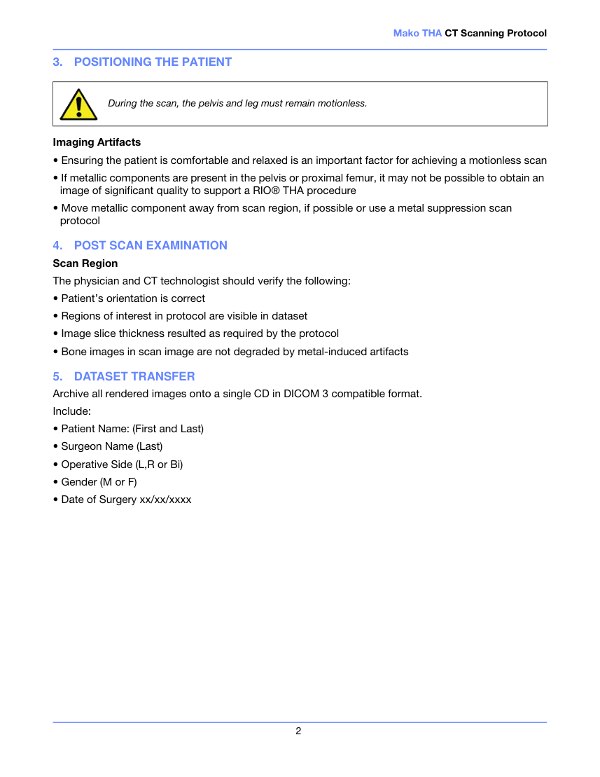
Mako THA CT Scanning Protocol 3. POSITIONING THE PATIENT During the scan, the pelvis and leg must remain motionless. Imaging Artifacts • Ensuring the patient is comfortable and relaxed is an important factor for achieving a motionless scan • If metallic components are present in the pelvis or proximal femur, it may not be possible to obtain an image of significant quality to support a RIO® THA procedure • Move metallic component away from scan region, if possible or use a metal suppression scan protocol 4. POST SCAN EXAMINATION Scan Region The physician and CT technologist should verify the following: • Patient’s orientation is correct • Regions of interest in protocol are visible in dataset • Image slice thickness resulted as required by the protocol • Bone images in scan image are not degraded by metal-induced artifacts 5. DATASET TRANSFER Archive all rendered images onto a single CD in DICOM 3 compatible format.
Include: • Patient Name: (First and Last) • Surgeon Name (Last) • Operative Side (L,R or Bi) • Gender (M or F) • Date of Surgery xx/xx/xxxx 2
Include: • Patient Name: (First and Last) • Surgeon Name (Last) • Operative Side (L,R or Bi) • Gender (M or F) • Date of Surgery xx/xx/xxxx 2