CT — Gleznă Prophecy (MCB)
Sursă și prelucrare editorială
- Proveniență
- 1 referință declarată
- Fidelitatea preluării
- Nedocumentată
- Revizuire medicală
- Nedocumentată
Referințele declarate nu confirmă singure fidelitatea preluării sau aprobarea protocolului pentru utilizare locală.
Detalii despre surse și verificări
MCB Radiology — 21 Prophecy Ankle
- Ediție / versiune a sursei
- Neprecizată
- Pagină / secțiune
- Pagini: 1–8
- Relația cu protocolul
- Document original importat integral; atribuirea autorilor rămâne cea din PDF.
- Data consultării
- 2026-09-27
Prelucrarea acestei pagini
- Mod de prelucrare
- Titlu și navigare în română; documentul sursă în engleză.; PDF original integral, previzualizare și text extras automat; fără completarea parametrilor clinici lipsă.
- Adaptări față de sursă
- Nedocumentate; absența evidenței nu confirmă o preluare integrală.
- Responsabil pentru prelucrare
- Neprecizat
- Atribuire existentă în pagină
- MCB Radiology (portalul sursă). Această atribuire nu identifică automat autorul sursei sau revizorul medical.
- Versiunea paginii
- mcb-324b15078284
- Actualizare declarată a paginii
- 2026-09-27 — distinctă de revizuirea medicală.
Verificarea fidelității: Nedocumentată
Revizuirea medicală: Nedocumentată
Documentul original MCB — Gleznă Prophecy
Protocol · 8 pagini · consultat la 2026-09-27.
Descarcă PDF-ul integral · Sursa MCB · Catalogul MCB pentru această modalitate
Instrucțiunile, valorile și ilustrațiile din documentul original sunt păstrate în engleză. Titlul și navigarea sunt în română.
Pagina 1
Pagina 2
Pagina 3
Pagina 4
Pagina 5
Pagina 6
Pagina 7
Pagina 8

Textul documentului original
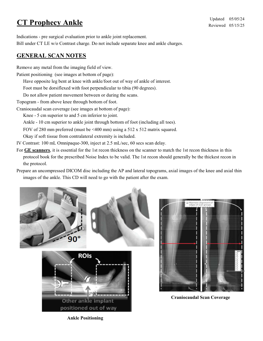
Pagina 1 — text în engleză
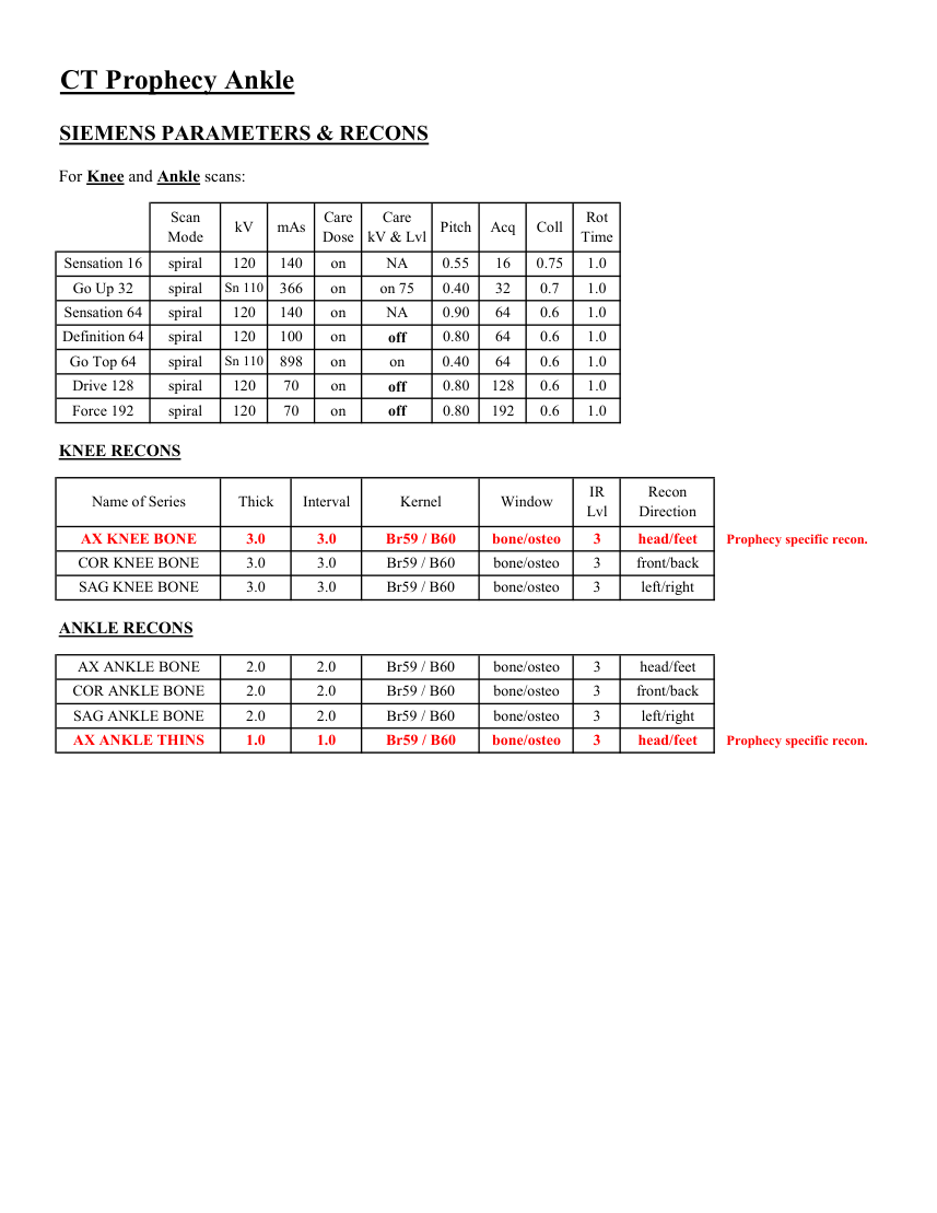
Pagina 2 — text în engleză
Care
Mode kV mAs Care
Dose kV & Lvl Pitch Acq Coll Rot Time Sensation 16 spiral 120 140 NA 0.55 on 0.75 16 1.0 Go Up 32 spiral Sn 110 366 on on 75 0.40 32 0.7 1.0 Sensation 64 spiral 120 140 on NA 0.90 64 0.6 1.0 Definition 64 spiral 120 100 on 0.6 1.0 0.80 64 off Go Top 64 spiral Sn 110 898 on on 0.40 64 0.6 1.0 Drive 128 spiral 120 70 on 0.80 128 0.6 1.0 off Force 192 spiral 120 70 on off 0.80 192 0.6 1.0 KNEE RECONS Recon
Name of Series Thick Interval Kernel Window IR
Lvl Direction Prophecy specific recon. AX KNEE BONE 3.0 3.0 Br59 / B60 bone/osteo 3 head/feet COR KNEE BONE 3.0 3.0 Br59 / B60 bone/osteo 3 front/back SAG KNEE BONE 3.0 3.0 Br59 / B60 bone/osteo 3 left/right ANKLE RECONS AX ANKLE BONE 2.0 2.0 Br59 / B60 bone/osteo 3 head/feet COR ANKLE BONE 2.0 2.0 Br59 / B60 bone/osteo 3 front/back SAG ANKLE BONE 2.0 2.0 Br59 / B60 bone/osteo 3 left/right Prophecy specific recon. AX ANKLE THINS 1.0 1.0 Br59 / B60 bone/osteo 3 head/feet
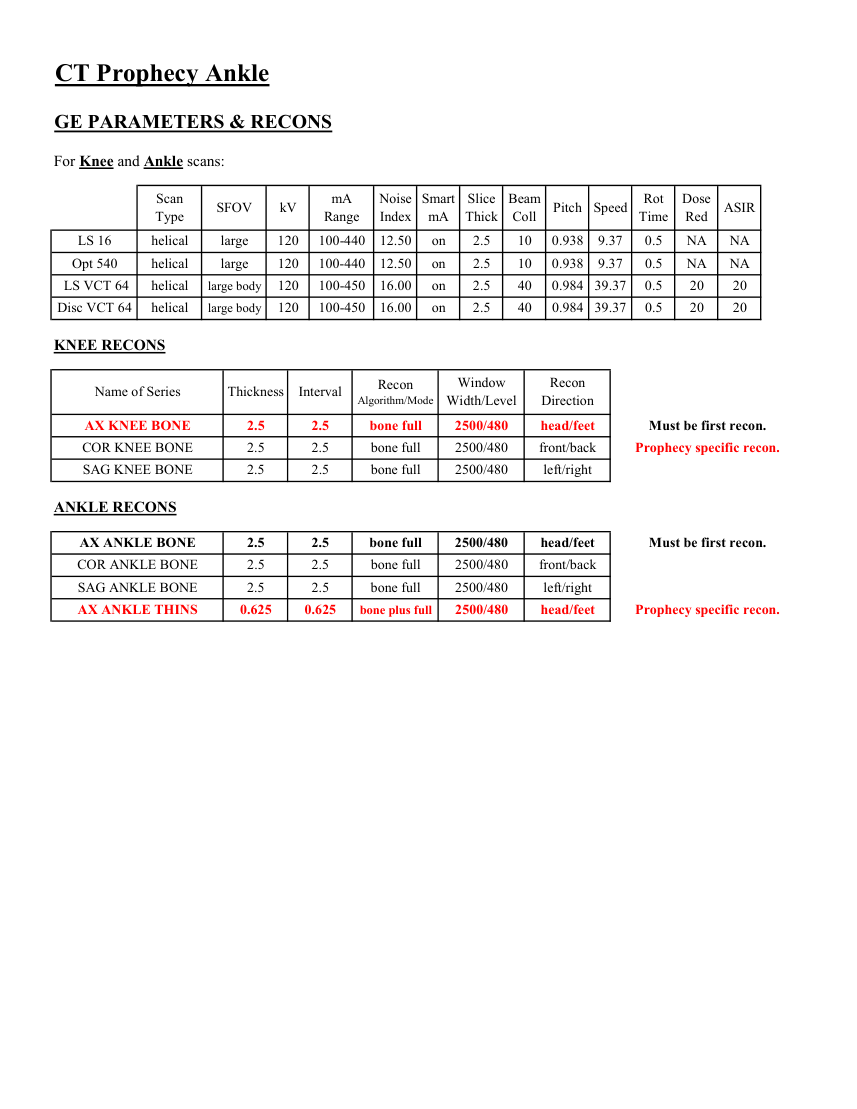
Pagina 3 — text în engleză
Slice
Beam
Dose
Type SFOV kV mA
Red ASIR Scan
Range Noise
Index mA Thick Coll Pitch Speed Rot
Time on 2.5 10 0.938 9.37 0.5 LS 16 helical large 120 100-440 12.50 NA NA Opt 540 helical large 120 100-440 12.50 on 2.5 10 0.938 9.37 0.5 NA NA LS VCT 64 helical large body 120 100-450 16.00 on 2.5 40 0.984 39.37 0.5 20 20 0.984 39.37 20 20 Disc VCT 64 helical large body 120 100-450 16.00 on 2.5 40 0.5 KNEE RECONS Window
Recon Name of Series Thickness Interval Recon
Algorithm/Mode Width/Level Direction AX KNEE BONE 2.5 2.5 bone full 2500/480 head/feet Must be first recon. COR KNEE BONE 2.5 2.5 bone full 2500/480 front/back Prophecy specific recon. SAG KNEE BONE 2.5 2.5 bone full 2500/480 left/right ANKLE RECONS AX ANKLE BONE 2.5 2.5 bone full 2500/480 head/feet Must be first recon. COR ANKLE BONE 2.5 2.5 bone full 2500/480 front/back SAG ANKLE BONE 2.5 2.5 bone full 2500/480 left/right AX ANKLE THINS 0.625 0.625 bone plus full 2500/480 head/feet Prophecy specific recon.
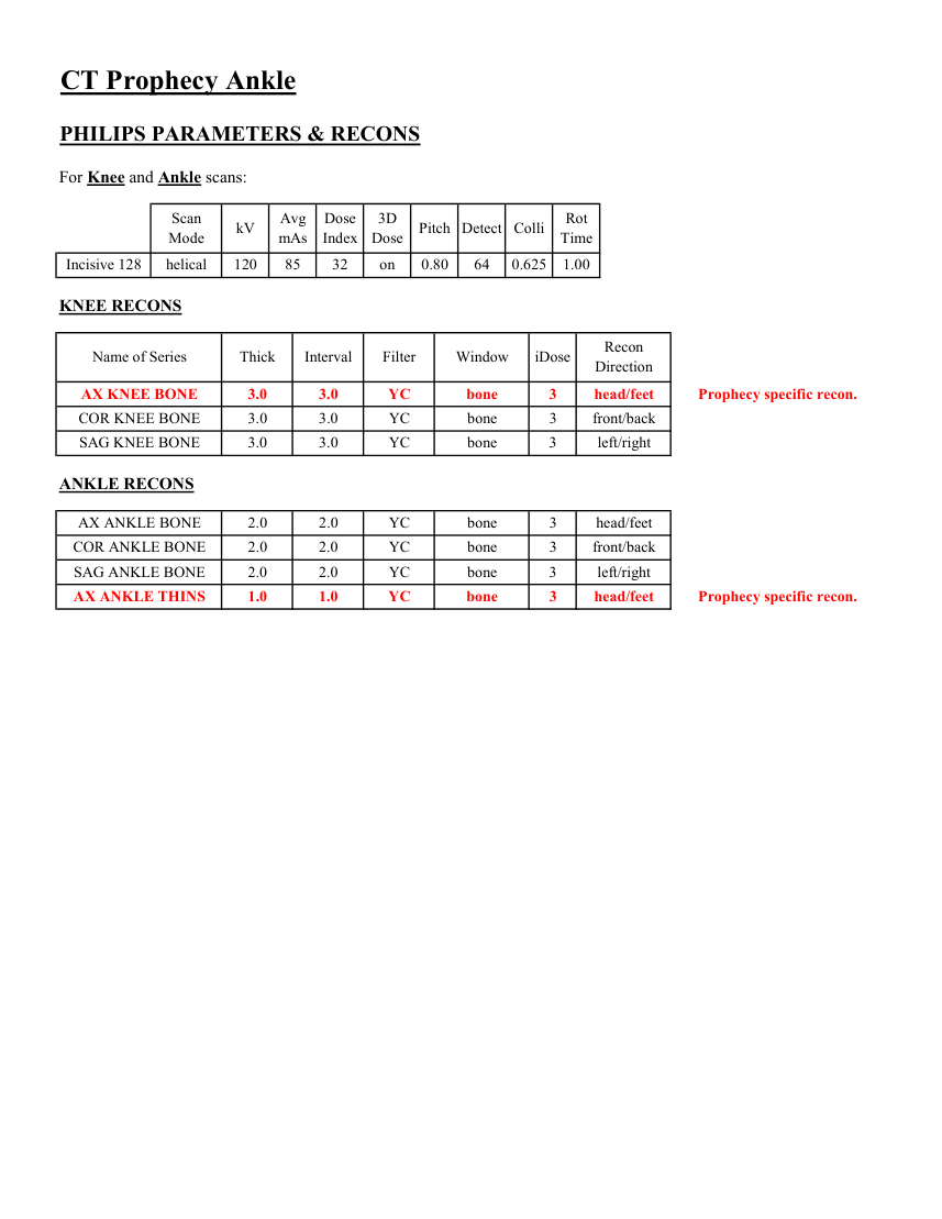
Pagina 4 — text în engleză
Dose
3D
Rot Mode kV Avg
mAs Index Dose Pitch Detect Colli Time Incisive 128 helical 120 85 32 on 0.80 64 0.625 1.00 KNEE RECONS Name of Series Thick Interval Filter Window iDose Recon
Direction AX KNEE BONE 3.0 3.0 YC bone 3 head/feet Prophecy specific recon. COR KNEE BONE 3.0 3.0 YC bone 3 front/back left/right SAG KNEE BONE 3.0 3.0 YC bone 3 ANKLE RECONS head/feet AX ANKLE BONE 2.0 2.0 YC bone 3 COR ANKLE BONE 2.0 2.0 YC bone 3 front/back SAG ANKLE BONE 2.0 2.0 YC bone 3 left/right AX ANKLE THINS 1.0 1.0 YC bone 3 head/feet Prophecy specific recon.
Pagina 5 — text în engleză
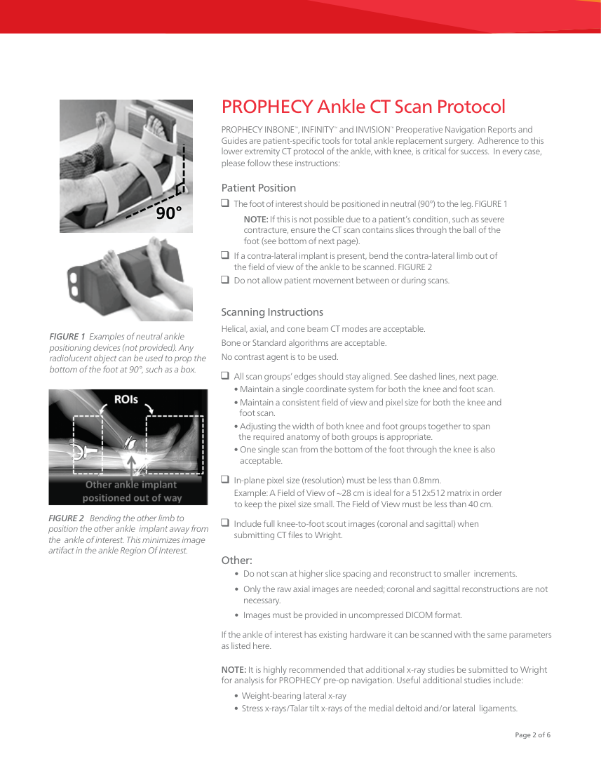
contracture, ensure the CT scan contains slices through the ball of the foot (see bottom of next page).
If a contra-lateral implant is present, bend the contra-lateral limb out of
the field of view of the ankle to be scanned. FIGURE 2 Do not allow patient movement between or during scans. Scanning Instructions Helical, axial, and cone beam CT modes are acceptable. Bone or Standard algorithms are acceptable. No contrast agent is to be used. FIGURE 1 Examples of neutral ankle positioning devices (not provided). Any radiolucent object can be used to prop the bottom of the foot at 90°, such as a box. FIGURE 1| Examples of neutral ankle positioning. All scan groups’ edges should stay aligned. See dashed lines, next page. • Maintain a single coordinate system for both the knee and foot scan. • Maintain a consistent field of view and pixel size for both the knee and
foot scan. • Adjusting the width of both knee and foot groups together to span
the required anatomy of both groups is appropriate. • One single scan from the bottom of the foot through the knee is also acceptable.
In-plane pixel size (resolution) must be less than 0.8mm. Example: A Field of View of ~28 cm is ideal for a 512x512 matrix in order
to keep the pixel size small. The Field of View must be less than 40 cm. Include full knee-to-foot scout images (coronal and sagittal) when
submitting CT files to Wright. FIGURE 2 Bending the other limb to position the other ankle
implant away from the ankle of interest. This minimizes image artifact in the ankle Region Of Interest.
Other: • Do not scan at higher slice spacing and reconstruct to smaller increments. • Only the raw axial images are needed; coronal and sagittal reconstructions are not necessary. • Images must be provided in uncompressed DICOM format. If the ankle of interest has existing hardware it can be scanned with the same parameters as listed here. NOTE: It is highly recommended that additional x-ray studies be submitted to Wright for analysis for PROPHECY pre-op navigation. Useful additional studies include:
• Weight-bearing lateral x-ray • Stress x-rays/Talar tilt x-rays of the medial deltoid and/or lateral ligaments. Page 2 of 6
Pagina 6 — text în engleză
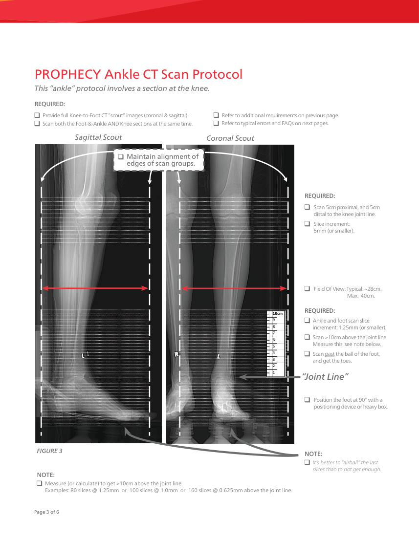
edges of scan groups. REQUIRED: Scan 5cm proximal, and 5cm distal to the knee joint line. Slice increment:
5mm (or smaller).
    Field Of View: Typical: ~28cm.
                          Max:  40cm.
REQUIRED: 10cm 9 8 Ankle and foot scan slice increment: 1.25mm (or smaller). 7 6 Scan >10cm above the joint line Measure this, see note below. 5 4 3 Scan past the ball of the foot, and get the toes. 2 1 “Joint Line” Position the foot at 90° with a positioning device or heavy box. FIGURE 3 NOTE: It’s better to “airball” the last slices than to not get enough. NOTE: Measure (or calculate) to get >10cm above the joint line. Examples: 80 slices @ 1.25mm or 100 slices @ 1.0mm or 160 slices @ 0.625mm above the joint line. Page 3 of 6
Pagina 7 — text în engleză
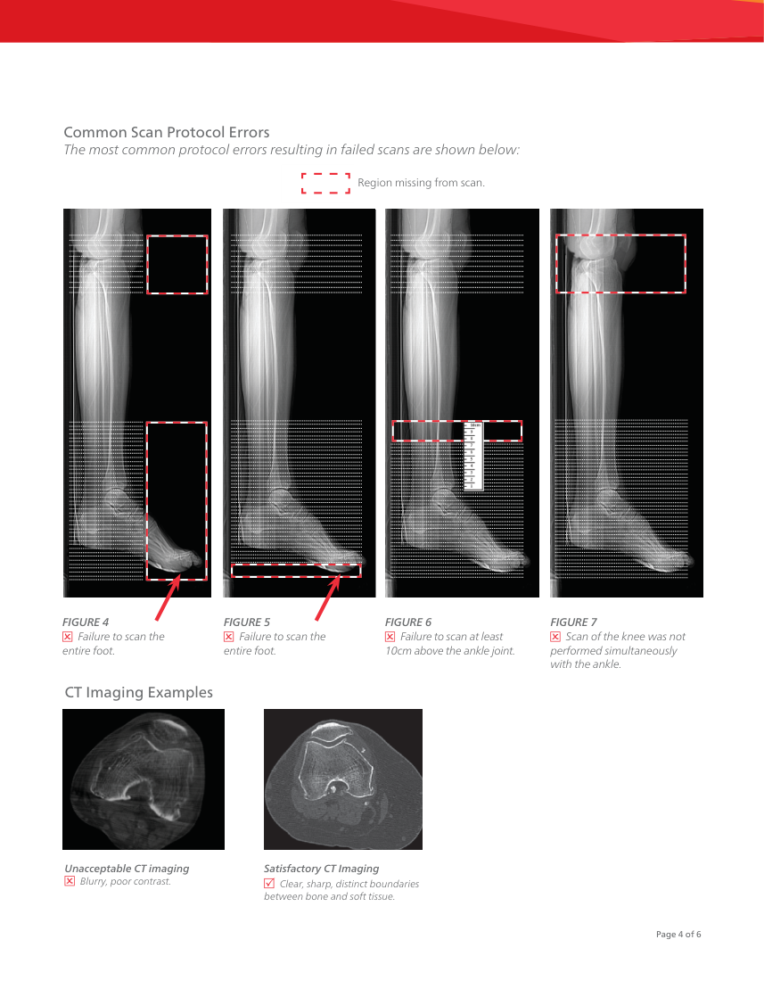
entire foot. Failure to scan the entire foot. Failure to scan at least 10cm above the ankle joint. Scan of the knee was not performed simultaneously with the ankle. CT Imaging Examples Unacceptable CT imaging Blurry, poor contrast. Satisfactory CT Imaging Clear, sharp, distinct boundaries
between bone and soft tissue. Page 4 of 6
Pagina 8 — text în engleză
Information based on the entire tibia is used to plan the ankle procedure. Q. “How should the patient be positioned?” A. Patients are typically supine for the scan, but it does not matter as long as the patient’s ankle is in neutral dorsiflexion. Submitting the Scan Rapid Electronic Scan Transfer Preoperative CT may be sent to the PROPHECY engineering team through our secure, rapid electronic transfer system: https://prophecyscans.wmt.com Please follow these steps to request an account and transfer scans: 1. E-mail [email protected] with the e-mail address of the person who needs access to the system (No other information is needed) 2. Within a few hours, an invitation message will be sent to that address with instructions to complete registration on the scan transfer site. ** upload times may vary based on connection speed. Scan submission is typically done by first putting the DICOM files from the CT Scanner computer onto a CD, then putting the CD into a typical office computer for uploading. Therefore, ensure the CD contains the Axial CT slices and full-length scout images.
FAQ: Can I mail the CD of the CT scan? A. This method is not preferred.
If uploading the scans directly from the scanning facility is not possible, please contact the local Wright Medical sales rep to do so. If the sales rep contact information is not known, call the number below. Contact for Assistance The Centers for Medicare & Medicaid Services (CMS) established a National Coverage Determination (NCD) for CT Scans. It states, in part, the following, “Diagnostic examinations of the head (head scans) and of other parts of the body (body scans) performed by computerized tomography (CT) scanners are covered if medical and scientific literature and opinion support the effective use of a scan for the condition, and the scan is: (1) reasonable and necessary for the individual patient.” CTs performed prior to total joint replacement procedures for diagnostic purposes may be considered medically necessary. In which case, the procedure should be billed using the CPT codes that accurately describe the imaging procedure furnished to the patient. These same images from the diagnostic CT scan may, in turn, be further utilized for developing the personalized cutting or navigation guides that are used in orthopaedic procedures. However, if providers perform CT scans solely for the purpose of developing personalized cutting instruments or guides, providers should contact the payer for billing and coverage guidance and/or the American College of Radiology with billing questions. PROPHECY Operations at Wright Medical Technology
Phone: 901.290.5884 Fax: 901.867.4791 email: [email protected] Page 5 of 6