CT — Genunchi Mako (MCB)
Sursă și prelucrare editorială
- Proveniență
- 1 referință declarată
- Fidelitatea preluării
- Nedocumentată
- Revizuire medicală
- Nedocumentată
Referințele declarate nu confirmă singure fidelitatea preluării sau aprobarea protocolului pentru utilizare locală.
Detalii despre surse și verificări
MCB Radiology — 17 Mako Knee
- Ediție / versiune a sursei
- Neprecizată
- Pagină / secțiune
- Pagini: 1–7
- Relația cu protocolul
- Document original importat integral; atribuirea autorilor rămâne cea din PDF.
- Data consultării
- 2026-09-27
Prelucrarea acestei pagini
- Mod de prelucrare
- Titlu și navigare în română; documentul sursă în engleză.; PDF original integral, previzualizare și text extras automat; fără completarea parametrilor clinici lipsă.
- Adaptări față de sursă
- Nedocumentate; absența evidenței nu confirmă o preluare integrală.
- Responsabil pentru prelucrare
- Neprecizat
- Atribuire existentă în pagină
- MCB Radiology (portalul sursă). Această atribuire nu identifică automat autorul sursei sau revizorul medical.
- Versiunea paginii
- mcb-819d449763bd
- Actualizare declarată a paginii
- 2026-09-27 — distinctă de revizuirea medicală.
Verificarea fidelității: Nedocumentată
Revizuirea medicală: Nedocumentată
Documentul original MCB — Genunchi Mako
Protocol · 7 pagini · consultat la 2026-09-27.
Descarcă PDF-ul integral · Sursa MCB · Catalogul MCB pentru această modalitate
Instrucțiunile, valorile și ilustrațiile din documentul original sunt păstrate în engleză. Titlul și navigarea sunt în română.
Pagina 1
Pagina 2
Pagina 3
Pagina 4
Pagina 5
Pagina 6
Pagina 7
Textul documentului original
Pagina 1 — text în engleză
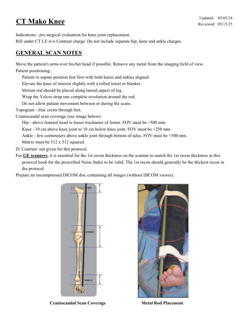
Updated 05/05/24 CT Mako Knee Reviewed 05/15/25 Indications - pre surgical evaluation for knee joint replacement. Bill under CT LE w/o Contrast charge. Do not include separate hip, knee and ankle charges. GENERAL SCAN NOTES Move the patient's arms over his/her head if possible. Remove any metal from the imaging field of view. Patient positioning: Patient in supine position feet first with both knees and ankles aligned. Elevate the knee of interest slightly with a rolled towel or blanket. Motion rod should be placed along lateral aspect of leg. Wrap the Velcro strap one complete revolution around the rod. Do not allow patient movement between or during the scans. Topogram - iliac crests through feet. Craniocaudal scan coverage (see image below): Hip - above femoral head to lesser trochanter of femur. FOV must be <500 mm. Knee - 10 cm above knee joint to 10 cm below knee joint. FOV must be <250 mm. Ankle - few centimeters above ankle joint through bottom of talus. FOV must be <500 mm. Matrix must be 512 x 512 squared. IV Contrast: not given for this protocol. For GE scanners, it is essential for the 1st recon thickness on the scanner to match the 1st recon thickness in this protocol book for the prescribed Noise Index to be valid. The 1st recon should generally be the thickest recon in the protocol. Prepare an uncompressed DICOM disc containing all images (without DICOM viewer). Craniocaudal Scan Coverage Metal Rod Placement
Pagina 2 — text în engleză
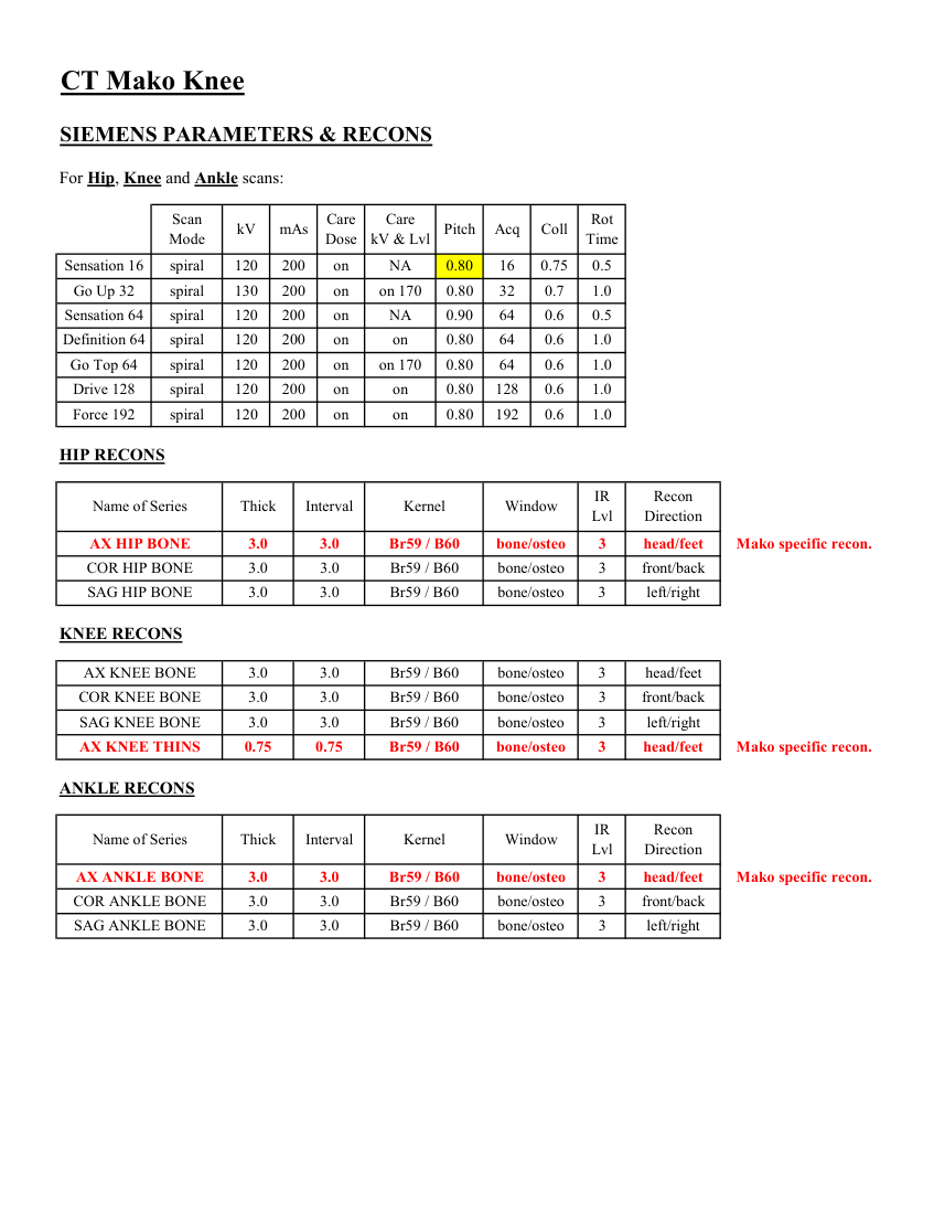
CT Mako Knee SIEMENS PARAMETERS & RECONS For Hip, Knee and Ankle scans: Scan
Care
Mode kV mAs Care
Dose kV & Lvl Pitch Acq Coll Rot Time Sensation 16 spiral 120 200 on NA 0.80 16 0.75 0.5 Go Up 32 spiral 130 200 on on 170 0.80 32 0.7 1.0 Sensation 64 spiral 120 200 on NA 0.90 64 0.6 0.5 Definition 64 spiral 120 200 on on 0.80 64 0.6 1.0 Go Top 64 spiral 120 200 on on 170 0.80 64 0.6 1.0 Drive 128 spiral 120 200 on on 0.80 128 0.6 1.0 1.0 Force 192 spiral 120 200 on on 0.80 192 0.6 HIP RECONS Recon
Name of Series Thick Interval Kernel Window IR
Lvl Direction AX HIP BONE 3.0 3.0 Br59 / B60 bone/osteo 3 head/feet Mako specific recon. COR HIP BONE 3.0 3.0 Br59 / B60 bone/osteo 3 front/back SAG HIP BONE 3.0 3.0 Br59 / B60 bone/osteo 3 left/right KNEE RECONS AX KNEE BONE 3.0 3.0 Br59 / B60 bone/osteo 3 head/feet COR KNEE BONE 3.0 3.0 Br59 / B60 bone/osteo 3 front/back SAG KNEE BONE 3.0 3.0 Br59 / B60 bone/osteo 3 left/right AX KNEE THINS 0.75 0.75 Br59 / B60 bone/osteo 3 head/feet Mako specific recon. ANKLE RECONS Recon
Name of Series Thick Interval Kernel Window IR
Lvl Direction AX ANKLE BONE 3.0 3.0 Br59 / B60 bone/osteo 3 head/feet Mako specific recon. COR ANKLE BONE 3.0 3.0 Br59 / B60 bone/osteo 3 front/back SAG ANKLE BONE 3.0 3.0 Br59 / B60 bone/osteo 3 left/right
Care
Mode kV mAs Care
Dose kV & Lvl Pitch Acq Coll Rot Time Sensation 16 spiral 120 200 on NA 0.80 16 0.75 0.5 Go Up 32 spiral 130 200 on on 170 0.80 32 0.7 1.0 Sensation 64 spiral 120 200 on NA 0.90 64 0.6 0.5 Definition 64 spiral 120 200 on on 0.80 64 0.6 1.0 Go Top 64 spiral 120 200 on on 170 0.80 64 0.6 1.0 Drive 128 spiral 120 200 on on 0.80 128 0.6 1.0 1.0 Force 192 spiral 120 200 on on 0.80 192 0.6 HIP RECONS Recon
Name of Series Thick Interval Kernel Window IR
Lvl Direction AX HIP BONE 3.0 3.0 Br59 / B60 bone/osteo 3 head/feet Mako specific recon. COR HIP BONE 3.0 3.0 Br59 / B60 bone/osteo 3 front/back SAG HIP BONE 3.0 3.0 Br59 / B60 bone/osteo 3 left/right KNEE RECONS AX KNEE BONE 3.0 3.0 Br59 / B60 bone/osteo 3 head/feet COR KNEE BONE 3.0 3.0 Br59 / B60 bone/osteo 3 front/back SAG KNEE BONE 3.0 3.0 Br59 / B60 bone/osteo 3 left/right AX KNEE THINS 0.75 0.75 Br59 / B60 bone/osteo 3 head/feet Mako specific recon. ANKLE RECONS Recon
Name of Series Thick Interval Kernel Window IR
Lvl Direction AX ANKLE BONE 3.0 3.0 Br59 / B60 bone/osteo 3 head/feet Mako specific recon. COR ANKLE BONE 3.0 3.0 Br59 / B60 bone/osteo 3 front/back SAG ANKLE BONE 3.0 3.0 Br59 / B60 bone/osteo 3 left/right
Pagina 3 — text în engleză
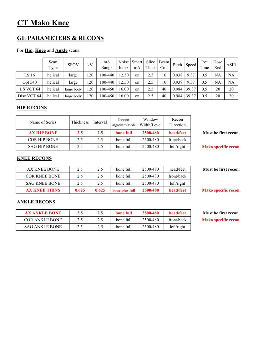
CT Mako Knee GE PARAMETERS & RECONS For Hip, Knee and Ankle scans: Scan
Smart
Slice
Beam
Rot
Dose
Pitch Speed Type SFOV kV mA
Range Noise
Index mA Thick Coll Time Red ASIR 10 0.938 9.37 0.5 LS 16 helical large 120 100-440 12.50 on 2.5 NA NA 2.5 Opt 540 helical large 120 100-440 12.50 on 10 0.938 9.37 0.5 NA NA LS VCT 64 helical large body 120 100-450 16.00 on 2.5 40 0.984 39.37 0.5 20 20 Disc VCT 64 helical large body 120 100-450 16.00 on 2.5 40 0.984 39.37 0.5 20 20 HIP RECONS Window
Recon Name of Series Thickness Interval Recon
Algorithm/Mode Width/Level Direction AX HIP BONE 2.5 2.5 bone full 2500/480 head/feet Must be first recon. COR HIP BONE 2.5 2.5 bone full 2500/480 front/back SAG HIP BONE 2.5 2.5 bone full 2500/480 left/right Mako specific recon. KNEE RECONS AX KNEE BONE 2.5 2.5 bone full 2500/480 head/feet Must be first recon. COR KNEE BONE 2.5 2.5 bone full 2500/480 front/back SAG KNEE BONE 2.5 2.5 bone full 2500/480 left/right AX KNEE THINS 0.625 0.625 bone plus full 2500/480 head/feet Mako specific recon. ANKLE RECONS AX ANKLE BONE 2.5 2.5 bone full 2500/480 head/feet Must be first recon. COR ANKLE BONE 2.5 2.5 bone full 2500/480 front/back Mako specific recon. SAG ANKLE BONE 2.5 2.5 bone full 2500/480 left/right
Smart
Slice
Beam
Rot
Dose
Pitch Speed Type SFOV kV mA
Range Noise
Index mA Thick Coll Time Red ASIR 10 0.938 9.37 0.5 LS 16 helical large 120 100-440 12.50 on 2.5 NA NA 2.5 Opt 540 helical large 120 100-440 12.50 on 10 0.938 9.37 0.5 NA NA LS VCT 64 helical large body 120 100-450 16.00 on 2.5 40 0.984 39.37 0.5 20 20 Disc VCT 64 helical large body 120 100-450 16.00 on 2.5 40 0.984 39.37 0.5 20 20 HIP RECONS Window
Recon Name of Series Thickness Interval Recon
Algorithm/Mode Width/Level Direction AX HIP BONE 2.5 2.5 bone full 2500/480 head/feet Must be first recon. COR HIP BONE 2.5 2.5 bone full 2500/480 front/back SAG HIP BONE 2.5 2.5 bone full 2500/480 left/right Mako specific recon. KNEE RECONS AX KNEE BONE 2.5 2.5 bone full 2500/480 head/feet Must be first recon. COR KNEE BONE 2.5 2.5 bone full 2500/480 front/back SAG KNEE BONE 2.5 2.5 bone full 2500/480 left/right AX KNEE THINS 0.625 0.625 bone plus full 2500/480 head/feet Mako specific recon. ANKLE RECONS AX ANKLE BONE 2.5 2.5 bone full 2500/480 head/feet Must be first recon. COR ANKLE BONE 2.5 2.5 bone full 2500/480 front/back Mako specific recon. SAG ANKLE BONE 2.5 2.5 bone full 2500/480 left/right
Pagina 4 — text în engleză
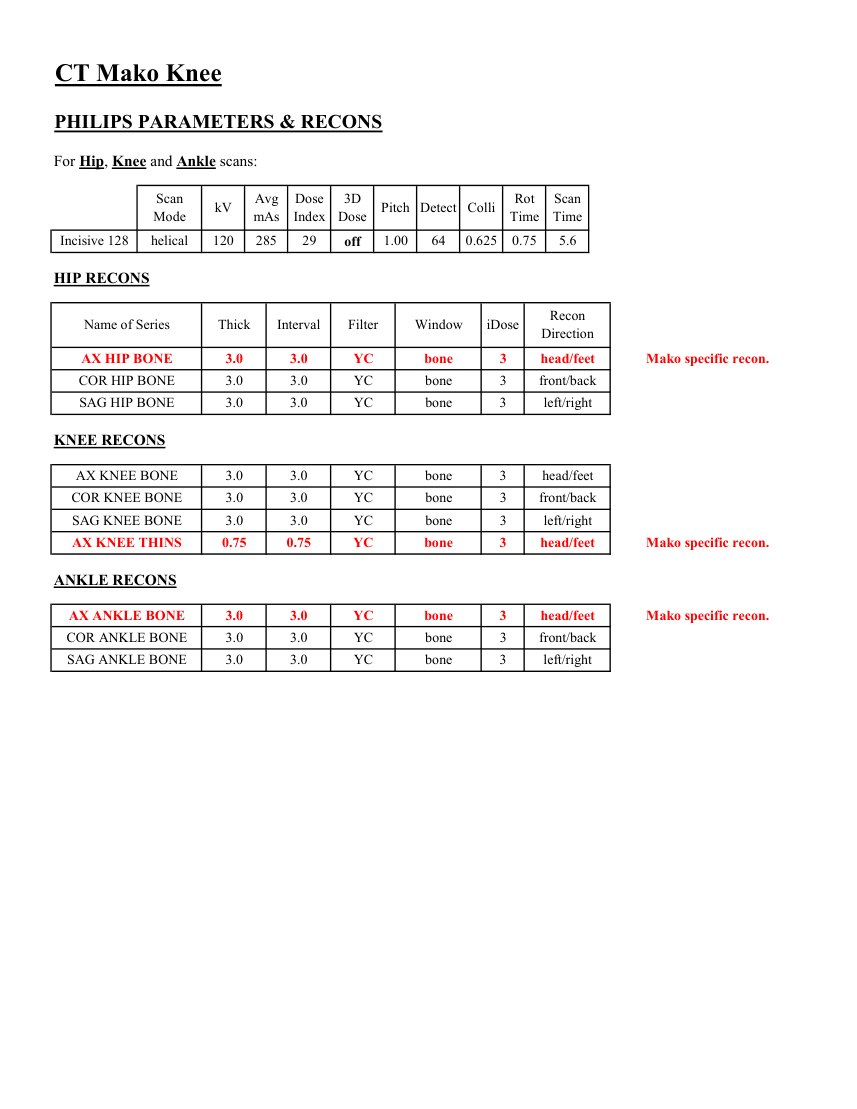
CT Mako Knee PHILIPS PARAMETERS & RECONS For Hip, Knee and Ankle scans: Scan
Dose
3D
Rot Scan
Mode kV Avg
mAs Index Dose Pitch Detect Colli Time Time 0.625 0.75 5.6 Incisive 128 helical 120 285 29 off 1.00 64 HIP RECONS Name of Series Thick Interval Filter Window iDose Recon
Direction AX HIP BONE 3.0 3.0 YC bone 3 head/feet Mako specific recon. COR HIP BONE 3.0 3.0 YC bone 3 front/back SAG HIP BONE 3.0 3.0 YC bone 3 left/right KNEE RECONS AX KNEE BONE 3.0 3.0 YC bone 3 head/feet COR KNEE BONE 3.0 3.0 YC bone 3 front/back SAG KNEE BONE 3.0 3.0 YC bone 3 left/right AX KNEE THINS 0.75 0.75 YC bone 3 head/feet Mako specific recon. ANKLE RECONS AX ANKLE BONE 3.0 3.0 YC bone 3 head/feet Mako specific recon. COR ANKLE BONE 3.0 3.0 YC bone 3 front/back SAG ANKLE BONE 3.0 3.0 YC bone 3 left/right
Dose
3D
Rot Scan
Mode kV Avg
mAs Index Dose Pitch Detect Colli Time Time 0.625 0.75 5.6 Incisive 128 helical 120 285 29 off 1.00 64 HIP RECONS Name of Series Thick Interval Filter Window iDose Recon
Direction AX HIP BONE 3.0 3.0 YC bone 3 head/feet Mako specific recon. COR HIP BONE 3.0 3.0 YC bone 3 front/back SAG HIP BONE 3.0 3.0 YC bone 3 left/right KNEE RECONS AX KNEE BONE 3.0 3.0 YC bone 3 head/feet COR KNEE BONE 3.0 3.0 YC bone 3 front/back SAG KNEE BONE 3.0 3.0 YC bone 3 left/right AX KNEE THINS 0.75 0.75 YC bone 3 head/feet Mako specific recon. ANKLE RECONS AX ANKLE BONE 3.0 3.0 YC bone 3 head/feet Mako specific recon. COR ANKLE BONE 3.0 3.0 YC bone 3 front/back SAG ANKLE BONE 3.0 3.0 YC bone 3 left/right
Pagina 5 — text în engleză
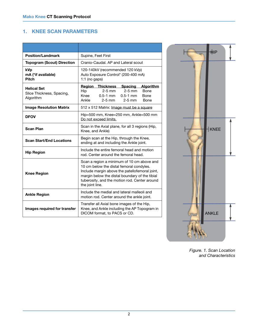
Mako Knee CT Scanning Protocol 1. KNEE SCAN PARAMETERS HIP Position/Landmark Supine, Feet First Topogram (Scout) Direction Cranio-Caudal. AP and Lateral scout 120-140kV (recommended 120 kVp) Auto Exposure Control (200-400 mA) 1:1 (no gaps) kVp mA (if available) Pitch Region Thickness Spacing Algorithm Helical Set Slice Thickness, Spacing, Algorithm Hip
2-5 mm 2-5 mm Bone Knee 0.5-1 mm 0.5-1 mm Bone Ankle
2-5 mm 2-5 mm Bone Image Resolution Matrix 512 x 512 Matrix: Image must be a square DFOV Hip=500 mm, Knee=250 mm, Ankle=500 mm Do not exceed limits. KNEE Scan Plan Scan in the Axial plane, for all 3 regions (Hip, Knee, and Ankle) Scan Start/End Locations Begin scan at the Hip, through the Knee, ending at and including the Ankle joint. Hip Region Include the entire femoral head and motion rod. Center around the femoral head. Knee Region Scan a region a minimum of 10 cm above and 10 cm below the distal femoral condyles. Include margin above the patellofemoral joint, margin below the distal boundary of the tibial tuberosity, and the motion rod. Center around the joint line. Ankle Region Include the medial and lateral malleoli and motion rod. Center around the ankle joint. Images required for transfer Transfer all Axial bone images of the Hip, Knee, and Ankle including the AP Topogram in DICOM format, to PACS or CD. ANKLE Figure. 1. Scan Location and Characteristics 2
2-5 mm 2-5 mm Bone Knee 0.5-1 mm 0.5-1 mm Bone Ankle
2-5 mm 2-5 mm Bone Image Resolution Matrix 512 x 512 Matrix: Image must be a square DFOV Hip=500 mm, Knee=250 mm, Ankle=500 mm Do not exceed limits. KNEE Scan Plan Scan in the Axial plane, for all 3 regions (Hip, Knee, and Ankle) Scan Start/End Locations Begin scan at the Hip, through the Knee, ending at and including the Ankle joint. Hip Region Include the entire femoral head and motion rod. Center around the femoral head. Knee Region Scan a region a minimum of 10 cm above and 10 cm below the distal femoral condyles. Include margin above the patellofemoral joint, margin below the distal boundary of the tibial tuberosity, and the motion rod. Center around the joint line. Ankle Region Include the medial and lateral malleoli and motion rod. Center around the ankle joint. Images required for transfer Transfer all Axial bone images of the Hip, Knee, and Ankle including the AP Topogram in DICOM format, to PACS or CD. ANKLE Figure. 1. Scan Location and Characteristics 2
Pagina 6 — text în engleză
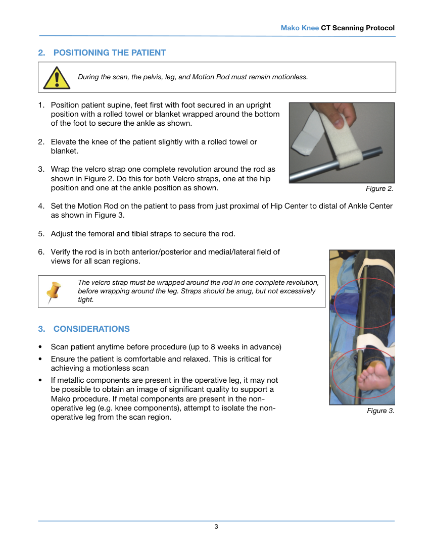
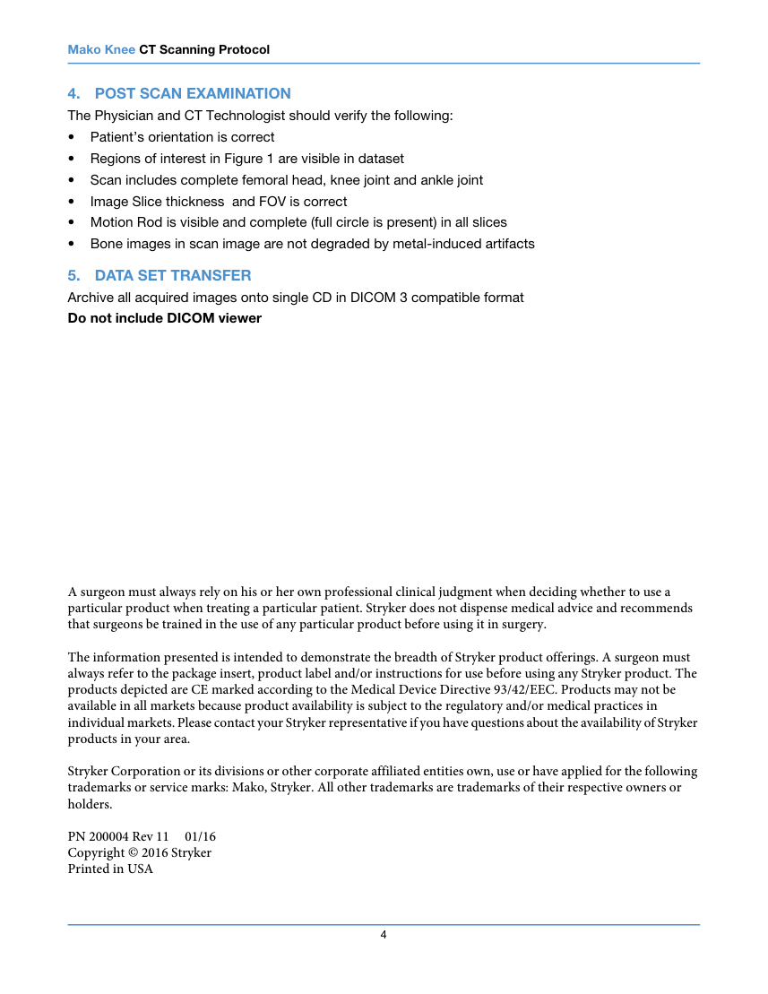
Mako Knee CT Scanning Protocol 2. POSITIONING THE PATIENT During the scan, the pelvis, leg, and Motion Rod must remain motionless. 1. Position patient supine, feet first with foot secured in an upright position with a rolled towel or blanket wrapped around the bottom of the foot to secure the ankle as shown. 2. Elevate the knee of the patient slightly with a rolled towel or blanket. 3. Wrap the velcro strap one complete revolution around the rod as shown in Figure 2. Do this for both Velcro straps, one at the hip position and one at the ankle position as shown. Figure 2. 4. Set the Motion Rod on the patient to pass from just proximal of Hip Center to distal of Ankle Center as shown in Figure 3. 5. Adjust the femoral and tibial straps to secure the rod. 6. Verify the rod is in both anterior/posterior and medial/lateral field of views for all scan regions. The velcro strap must be wrapped around the rod in one complete revolution, before wrapping around the leg. Straps should be snug, but not excessively tight. 3. CONSIDERATIONS • Scan patient anytime before procedure (up to 8 weeks in advance) • Ensure the patient is comfortable and relaxed. This is critical for achieving a motionless scan Figure 3. • If metallic components are present in the operative leg, it may not be possible to obtain an image of significant quality to support a Mako procedure. If metal components are present in the non- operative leg (e.g. knee components), attempt to isolate the non- operative leg from the scan region. 3
Pagina 7 — text în engleză
Mako Knee CT Scanning Protocol 4. POST SCAN EXAMINATION The Physician and CT Technologist should verify the following: • Patient’s orientation is correct • Regions of interest in Figure 1 are visible in dataset • Scan includes complete femoral head, knee joint and ankle joint • Image Slice thickness and FOV is correct • Motion Rod is visible and complete (full circle is present) in all slices • Bone images in scan image are not degraded by metal-induced artifacts 5. DATA SET TRANSFER Archive all acquired images onto single CD in DICOM 3 compatible format Do not include DICOM viewer A surgeon must always rely on his or her own professional clinical judgment when deciding whether to use a particular product when treating a particular patient. Stryker does not dispense medical advice and recommends that surgeons be trained in the use of any particular product before using it in surgery. The information presented is intended to demonstrate the breadth of Stryker product offerings. A surgeon must always refer to the package insert, product label and/or instructions for use before using any Stryker product. The products depicted are CE marked according to the Medical Device Directive 93/42/EEC. Products may not be available in all markets because product availability is subject to the regulatory and/or medical practices in individual markets. Please contact your Stryker representative if you have questions about the availability of Stryker products in your area. Stryker Corporation or its divisions or other corporate affiliated entities own, use or have applied for the following trademarks or service marks: Mako, Stryker. All other trademarks are trademarks of their respective owners or holders. PN 200004 Rev 11 01/16 Copyright © 2016 Stryker Printed in USA 4